
Implementing and Administering Cisco Solutions


1. Exploring the Functions of Networking
Components of a Network
- Endpoints: PC, Laptop, Server, HP, TV, Servers dll
- Intermediary Devices: Switchs, Routers, APs, WLCs, Firewalls, IPS
- Media: Ethernet Link, Serial Link, Wireless
- Network Services: Email, Web, Application
Characteristics of a Networking
- Topology: is the arrangement of its elements.
- Bitrate or Bandwidth: measures the data rate in bits per second (bps) of a given link in the network.
- Availability: indicates how much time a network is accessible and operational.
-
Reliability: indicates how well the network operates.
Total Uptime in a Day in a Minutes 55 ----------------------------------- = --------- = 91% Total minutes in a Day 60 - Scalability: indicates how easily the network can accommodate more users and data transmission requirements without affecting current network performance.
- Security: how well the network is defended from potential threats.
- QoS: includes tools, mechanisms, and architectures, which allow you to control how and when applications use network resources.
- Cost: indicates the general expense for the initial purchase of the network components and any costs associated with installing and maintaining these components.
- Virtualization: creates a software solution that emulates network services and functions.
Physical vs Logical Topology
- Physical Topology:
- Bus: every workstation is connected to a common transmission medium, a single cable, which is called a backbone or bus.
- Ring: computers and other network devices are cabled in succession, and the last device is connected to the first one to form a circle or ring.
- Star: there is a central device to which all other network devices connect via point-to-point links.
- Mesh: a device can be connected to more than one other device.
- Logical Topology: the path which data travels from one point in the network to another.
Classify Application, Traffic, & Performance are described in below classification
- Interactivity: Applications can be interactive or noninteractive.
- Real-time responsiveness: Real-time applications expect a timely data serving, and they are not necessarily interactive.
- Amount of data generated: Some applications produce a low quantity of data, such as voice applications.
- Burstiness: Applications that always generate a consistent amount of data are referred to as smooth or nonbursty applications.
- Drop sensitivity: Packet loss is losing packets along the data path, which can severely degrade the application performance.
- Criticality to business: This aspect of an application is “subjective” in that it depends on someone’s estimate of how valuable and important the application is to a business.
Application classification (Example)
- Batch applications: FTP, TFTP, inventory updates.
- Interactive applications: database inquiry, stock exchange transaction
- Real-time applications: Voice applications, video conferencing, and online streaming such as live sports.
2. Introducing the Host-to-Host Communication Model
Layered models provide several benefits:
- Make complexity manageable by breaking communication tasks into smaller, simpler functional groups.
- Define and specify communication tasks to provide the same basis for everyone to develop their own solutions.
- Facilitate modular engineering, allowing different types of network hardware and software to communicate with one another.
- Prevent changes in one layer from affecting the other layers.
- Accelerate evolution, providing for effective updates and improvements to individual components without affecting other components or having to rewrite the entire protocol.
- Simplify teaching and learning.
ISO OSI Reference Model
- Layer 1: Physical Layer defines electrical, mechanical, procedural, and functional specifications for activating, maintaining, and deactivating the physical link between devices. (Ethernet)
- Layer 2: Data Link Layer defines how data is formatted for transmission and controlled access to physical media. This layer uses a physical address, sometimes called a MAC address, to identify hosts on the local network. (Ethernet)
- Layer 3: Network Layer provides connectivity and path selection beyond the local segment, all the way from the source to the final destination. uses logical addressing to manage connectivity. (IP, ARP, ICMP, IGMP)
- Layer 4: Transport Layer defines segmenting and reassembling of data belonging to multiple individual communications, defines the flow control, and defines the mechanisms for reliable transport if required. (TCP, UDP)
- Layer 5: Session Layer establishes, manages, and terminates sessions between two communicating hosts to allow them to exchange data over a prolonged time period. (HTTP, FTTP, Telnet, NTP, DHCP, PING)
- Layer 6: Presentation Layer ensures that data sent by the application layer of one system is “readable” by the application layer of another system. (HTTP, FTTP, Telnet, NTP, DHCP, PING)
- Layer 7: Application Layer provides services to user applications that want to use the network. (HTTP, FTTP, Telnet, NTP, DHCP, PING)
TCP/IP Protocol Suite
- Link Layer: Controls the hardware devices and media that make up the network (Ethernet)
- Internet Layer: Provides logical addressing and determines the best path through the network (IP, ARP, ICMP, IGMP)
- Transport Layer: Support communication between and devices across a diverse network (TCP, UDP)
- Application Layer: Represents data users, encodes, and controls the dialog. (HTTP, FTTP, Telnet, NTP, DHCP, PING)
PDUs (Protocol Data Units) naming in each layer
- Data: Application layer (DATA)
- Segment: Transport layer (TCP/UDP)
- Packet: Internet layer (IP)
- Frame: Link layer (MACS)
Encapsulation and Deencapsulation
  [FRAME HEADER]4 | [IP HEADER]3 | [TCP HEADER]2 | [DATA]1 | [CRC/FCS]4

  DATA --> SEGMENT --> PACKETS --> FRAME
3. Operating Cisco IOS Software
CISCO IOS Software deliver following features:
- Support for basic and advanced networking functions and protocols
- Connectivity for high-speed traffic transmission
- Security for access control and prevention of unauthorized network use
- CLI-based and GUI-based access enabling users to execute configuration commands
- Scalability to allow adding hardware and software components
- Reliability to ensure dependable access to networked resources
Cisco IOS Software CLI Functions
- The CLI is used to enter commands.
- Operations vary on different internetworking devices.
- Users type in or copy and paste entries in the console command modes.
- Command modes have distinctive prompts.
- Pressing Enter instructs the device to parse (translate) and execute the command.
- The two primary EXEC modes are user mode and privileged mode
CLI primary access levels
- User EXEC: Allows a person to execute only a limited number of basic monitoring commands.
- Privileged EXEC: Allows a person to execute all device commands, for example, all configuration and management commands. This level can be password protected.
- Global Configuration Mode: Use this mode to configure parameters that apply to the entire device.
- Interface Configuration Mode: Use this mode to configure parameters for the device interfaces.
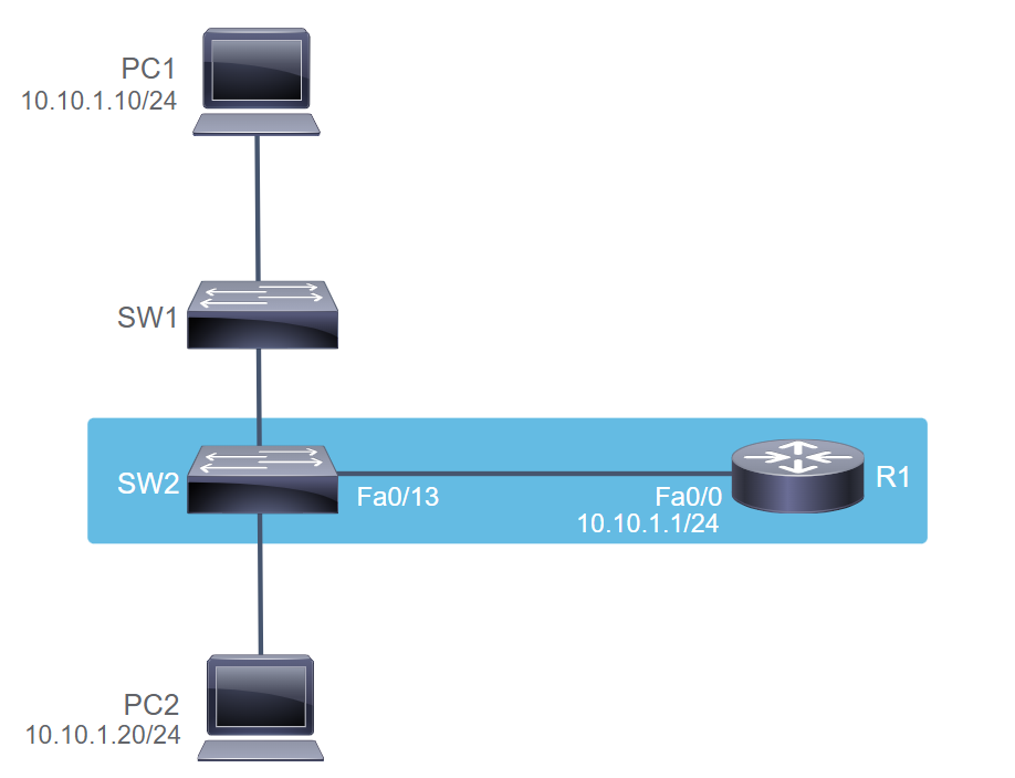
  SW1> en
  SW1# conf t
  SW1(config)# int eth 0/0
  SW1(config-if)# desc link to SW2
4. Introducing LANs
LAN fundamental components:
- Hosts: include any device that can send or receive data on the LAN.
-
Interconnections: allow data to travel from one point to another in the network.
- NICs
- Network Media
-
Network Devices: are responsible for data delivery between hosts.
- Switches
- Routers
- APs
- Protocols: are rules that govern how data is transmitted between components of a network. Eth Protocols, IP, TCP, UDP, ARP, CIFS, NDP, DHCP
Function of LAN:
- Data and Applications: can share files and even software applications
- Resources: can be shared include input devices, such as cameras, and output devices, such as printers.
- Communication path to other networks: can provide connectivity via a gateway to remote resources, such as the internet.
Common cause network congestion:
- Increasingly powerful computer and network technologies
- Increasingly volume of network traffic
- High-bandwidth application
Switches features and functions
- Operate at the link layer of the TCP/IP protocol suite
- Selectively forward individual frames
- Have many ports to segment a large LAN into many smaller segments
- Have high speed and support various port speeds
Switch Importance functions
- Dedicated Communication between devices: increases frame throughput.
- Multiple Simultaneous conversations: Multiple simultaneous conversations can occur by forwarding or switching several packets at the same time, increasing network capacity by the number of conversations that are supported.
- Full-duplex communication: now possible to configure the ports so they can both receive and send data at the same time.
- Media-rate Adaptation: has ports with different media rates can adapt to between rates.
Important characteristics of switches
- High port density: switches have high port densities: 24-, 32-, and 48-port switches operate at high speeds
- Large frame buffers: have ability to store more received frames before having to start dropping them is useful, particularly when there may be congested ports connected to servers or other heavily used parts of the network.
- Port speed: port speed may be possible to support a range of bandwidths.
- Fast Internal switching: having fast internal switching allows higher bandwidths.
- Low per-port cost: switches provide high port density at a lower cost. can accommodate network designs that feature fewer users per segment and increase the average available bandwidth per user.
5. Exploring the TCP/IP Link Layer
Ethernet LAN Connection Media
- Standard Name
- 1000 transmission speed 1000Mbps or 1Gbps
- BASE baseband signaling (only Ethernet signal on the media)
- T represent twisted-pair cable
- Type of Physical Media
- Coaxial Cable (No longer used)
-
Copper Media
- Unshielded Twisted-Pair Cable: Cat5 (100Mbps), Cat5e (up to 1Gbps), Cat6 (copper up to 10Gbps), Cat6e (up to 10Gbps), Cat7 (up to 10Gbps), Cat8 (up to 40Gbps)
- RJ-45 Connector and Jack: UTP cables are used with RJ-45 connectors.
- Power over Ethernet describes systems that pass electric power along with data on Ethernet cabling.
- Straight-Through or Crossover UTP Straight (different device) & Crossover (same device)
-
Optical Fiber
- Fiber Types Multimode Fiber (MMF) & Singlemode Fiber (SMF)
- Fiber connection types Threaded, Bayonet, Push-pull
- SFP & SFP+ Transceivers SFP (1Gbps) & SFP+ (10Gbps)
Ethernet II Frame
- Preamble 8 bytes to synchronize the signal
- Destination Address (DA) 6 bytes destination NIC MAC Address
- Source Address(SA): 6 bytes source NIC MAC Address
- Type: 2 bytes identify network layer protocol (TCP/UDP)
- Payload: contains network layer data
-
FCS: 4 bytes checking mechanism to ensure no corruption
[Preamble] | [Destination MAC] | [Source MAC] | [Type] | [Payload] | [FCS]
Three Major Types of Network Communication
- Unicast frame is sent from one host and is addressed to one specific destination.
- Broadcast frame is sent from one address to all other addresses.
- Multicast information is sent to a specific group of devices or clients.
MAC Address formats
-
24-bit OUI: OUI identifies the manufacturer of the NIC.
- Broadcast / Multicast bit: the least significant bit in the first octet of the MAC address is 1, it indicates to the receiving interface that the frame is destined for all (broadcast) or a group of (multicast) end stations on the LAN segment.
- Locally Administered address bit: the second least significant bit of the first octet of the MAC address is referred as a universally or locally (U/L) administered address bit.
- 24-bit vendor-assigned & end-station Address: this portion uniquely identifies the Ethernet hardware.
Frame Switching procedure
- The switch receives a frame from PC A on port 1.
- The switch enters the source MAC address (of PC A) and the switch port that received the frame into the MAC table.
- The switch checks the table for the destination MAC address (of PC B). Because the destination address is not known, the switch floods the frame to all the ports except the port on which it received the frame. In this example, both PC B and PC C will receive the frame.
- The destination device with the matching MAC address (PC B) replies with a unicast frame addressed to PC A.
- The switch enters the source MAC address of PC B and the port number of the switch port that received the frame into the MAC table. The destination address of the frame (PC A) and its associated port are found in the MAC table.
- The switch can now forward frames between the source and destination devices (PC A and PC B) without flooding because it has entries in the MAC table that identify the associated ports.
How Switch Operates
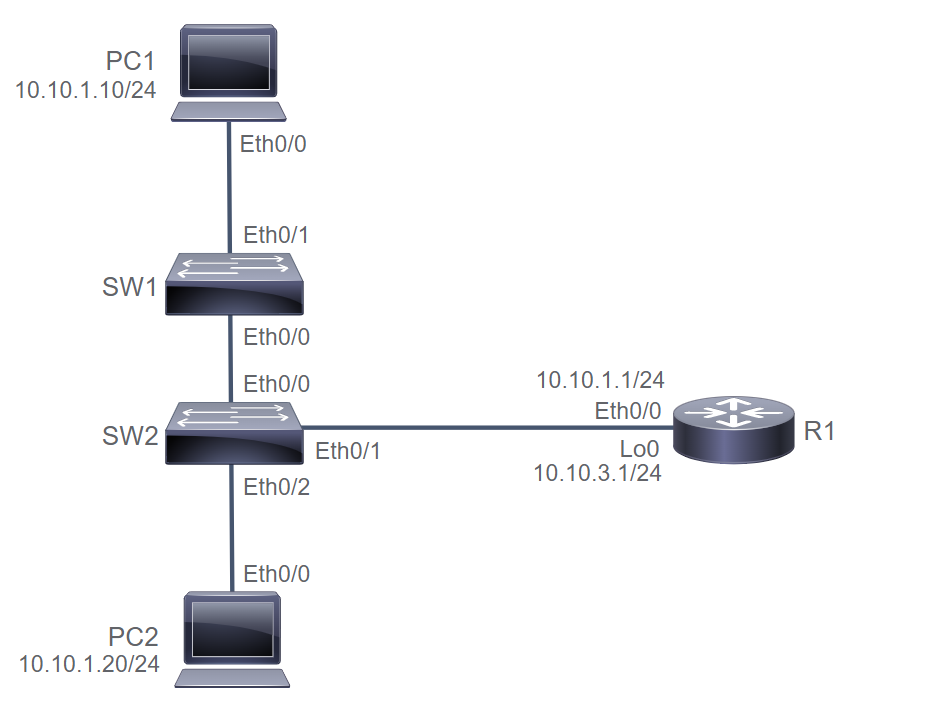
PC1# show interface e0/0 | include address
Hardware is AmdP2, address is aabb.cc00.7600 (bia aabb.cc00.7600)
Internet address is 10.10.1.10/24

PC2# show interface e0/0 | include address
Hardware is AmdP2, address is aabb.cc00.7700 (bia aabb.cc00.7700)
Internet address is 10.10.1.20/24

R1# show interface e0/0 | include address
Hardware is AmdP2, address is aabb.cc00.7500 (bia aabb.cc00.7500)
Internet address is 10.10.1.1/24

SW2# show mac address-table
          Mac Address Table
-------------------------------------------

Vlan    Mac Address       Type        Ports
----    -----------       --------    -----
   1    aabb.cc00.7500    DYNAMIC     Et0/1
   1    aabb.cc00.7700    DYNAMIC     Et0/2
Total Mac Addresses for this criterion: 2

SW2# clear mac address-table dynamic
SW2# show mac address-table
          Mac Address Table
-------------------------------------------

Vlan    Mac Address       Type        Ports
----    -----------       --------    -----
   1    aabb.cc00.7500    DYNAMIC     Et0/1
   1    aabb.cc00.7700    DYNAMIC     Et0/2
Total Mac Addresses for this criterion: 2

SW1# clear mac address-table dynamic
SW1# show mac address-table
          Mac Address Table
-------------------------------------------

Vlan    Mac Address       Type        Ports
----    -----------       --------    -----
   1    aabb.cc00.7600    DYNAMIC     Et0/1
Total Mac Addresses for this criterion: 1

PC1# ping 10.10.1.1
Type escape sequence to abort.
Sending 5, 100-byte ICMP Echos to 10.10.1.1, timeout is 2 seconds:
!!!!!
Success rate is 100 percent (5/5), round-trip min/avg/max = 1/1/1 ms

PC1# ping 10.10.1.20
Type escape sequence to abort.
Sending 5, 100-byte ICMP Echos to 10.10.1.20, timeout is 2 seconds:
.!!!!
Success rate is 80 percent (4/5), round-trip min/avg/max = 1/2/5 ms

SW1# show mac address-table
          Mac Address Table
-------------------------------------------

Vlan    Mac Address       Type        Ports
----    -----------       --------    -----
   1    aabb.cc00.7500    DYNAMIC     Et0/0
   1    aabb.cc00.7600    DYNAMIC     Et0/1
   1    aabb.cc00.7700    DYNAMIC     Et0/0
Total Mac Addresses for this criterion: 3

SW2# show mac address-table
          Mac Address Table
-------------------------------------------

Vlan    Mac Address       Type        Ports
----    -----------       --------    -----
   1    aabb.cc00.7500    DYNAMIC     Et0/1
   1    aabb.cc00.7600    DYNAMIC     Et0/0
   1    aabb.cc00.7700    DYNAMIC     Et0/2
Total Mac Addresses for this criterion: 3
Duplex Communications
- Half Duplex: Unidirectional data flow, Legacy connectivity, May have collision issues
- Full Duplex: Point-to-point only, Attached to a dedicated switched port, Requires full-duplex support on both ends
-
Duplex Command
SW1(config)# int fa0/1
SW1(config-if)# duplex full
SW1(config-if)# speed 100
SW1(config)# int fa0/2
SW1(config-if)# duplex half
SW1(config-if)# speed 100
SW1(config)# int fa0/3
SW1(config-if)# duplex auto
SW1(config-if)# speed auto

SwitchX# show interfaces FastEthernet0/5
FastEthernet0/5 is up, line protocol is up (connected)
Full-duplex, 100Mb/s, media type is 10/100BaseTX
6. Starting Switch
Switch Physical Installation:
- Before physical installation, verify power requirements and operating environment requirement
- Physical Installation
- Verify network cables that provide connectivity
- Attach power cable plug to the power supply socket of the switchs
- System startup routines perform POST and initiate the switch software
Basic Show Commands
- Switch
bashow InterfaceCommandSW1# show interface FastEthernet 0/1 FastEthernet0/1 is up, line protocol is up (connected) --> status Hardware is Fast Ethernet, address is 001e.147c.bd01 (bia 001) --> MAC Address Full-duplex, 100Mb/s, media type is 10/100BaseTX --> Connection Mode 5 minute input rate 31000 bits/sec, 33 packets/sec --> interface traffic SW1# sh int SW1# sh ip int br - Switch
bashow VersionCommandSW1# show version Cisco IOS Software, C2960 Software (C2960-LANBASEK9-M) --> Cisco IOS Version SW1 uptime is 15 hours, 30 minutes --> Switch Uptime System image file is "flash:/c2960-lanbasek9-mz.150-1.SE3..." --> System Image File cisco WS-C2960-24TT-L (PowerPC405) processor (revision D0) ... --> Hardware information Processor board ID FOC1141Z8YW ---> Device Serial Number - Switch
bashow Running-configCommandSW1# show running-config interface Vlan1 ip address 172.20.137.5 255.255.255.0 ! ip default-gateway 172.20.137.1
Perform Basic Command
  Switch> en
  Switch# conf t
  Switch(config)# hostname SW1

  # Add IP to interface VLAN 1
  SW1(config)# int VLAN 1
  SW1(config-if)# ip add 10.10.1.2 255.255.255.0
  SW1(config-if)# no shut
  SW1(config-if)# do sh ip int br
  SW1(config-if)# do sh vlan
  SW1(config-if)# exit

  # Add IP default gateway
  SW1(config)# ip default-gateway 10.10.1.1
  SW1(config)# do sh ip int br
  SW1(config)# do sh run int vlan 1
  SW1(config)# do sh ip int vlan 1
  SW1(config)# do sh int vlan 1

  # Show gateway and change switch to router
  SW1# sh ip ro
  SW1# sh run | i default
  SW1# ping 10.10.3.1 --> ping different subnet (worked)
  SW1# conf t
  SW1(config)# ip routing --> change SW1 into a router (L3)
  SW1(config)# do sh ip ro --> gateway not set, when change into router
  SW1(config)# no ip routing --> change back to switch mode (L2)
  SW1(config)# do sh ip ro --> ip default gateway is back and become SW1 again

  # Add decription on each interface
  SW1(config)# int e0/0
  SW1(config)# desc Link to SW2
  SW1(config)# int e0/1
  SW1(config)# desc Link to PC1
  SW1(config)# do sh int status --> you will see name & desc in interface

  # Save running-config to startup config
  SW1# copy running-config startup-config --> or
  SW1# write
7. Introducing the TCP/IP Internet Layer, IPv4 Addressing, and Subnets
IP has these characteristics:
- IP operates at Layer 3 or the network layer of the Open Systems Interconnection (OSI) reference model (network layer) and at the Internet layer of the TCP/IP stack.
- IP is a connectionless protocol, in which a one-way packet is sent to the destination without advance notification to the destination device. The destination device receives the data and does not return any status information to the sending device.
- Each packet is treated independently, which means that each packet can travel a different way to the destination.
- IP uses hierarchical addressing, in which the network identification is the equivalent of a street, and the host ID is the equivalent of a house or an office building on that street.
- IP provides service on a best-effort basis and does not guarantee packet delivery. A packet can be misdirected, duplicated, or lost on the way to its destination.
- IP does not provide any special features that recover corrupted packets. Instead, the end systems of the network provide these services.
- IP operates independently of the medium that is carrying the data.
- There are two types of IP addresses: IPv4 and IPv6—the latter becoming increasingly important in modern networks.
Decimal Binary Conversion
| Base | 27 | 26 | 25 | 24 | 23 | 22 | 21 | 20 |
|---|---|---|---|---|---|---|---|---|
| Value | 128 | 64 | 32 | 16 | 8 | 4 | 2 | 1 |
| Dec to Bin | 1 | 0 | 1 | 1 | 0 | 0 | 0 | 0 |
IP4 Address consist of two parts:
- Network ID: most hosts on a network can communicate only with devices in the same network. Router/multilayer switch can route data between the networks.
- Host ID: are assigned to individual devices, both hosts or endpoints and intermediary devices.
IPv4 Header Fields
- 4 fields modified continually in transit:
- Service Type: provides information on the desired quality of service
- TTL: Limits the lifetime of a packet
- Source address: 32bit represents the sending endpoint
- Destination address: 32bit represents the receiving endpoint
- other static header:
- Version: Describes the version of IP.
- IHL: Internet Header Length (IHL) describes the length of the header.
- Total Length: Describes the length of a packet, including header and data.
- Identification: Used for unique fragment identification.
- Flag: Sets various control flags regarding fragmentation.
- Fragment Offset: Indicates where a specific fragment belongs.
- Protocol: Indicates the upper-layer protocol that is used in the data portion of an IPv4 packet.
- Header Checksum: Used for header error detection.
- Options: Includes optional parameters
- Padding: Used to ensure that the header ends on a 32-bit boundary
IPv4 Address Classes
- Class A: designed to support extremely large networks with more than 16Mio host address. Range from 0.0.0.0 to 127.255.255.255.
- Class B: designed to support moderate to large networks with more than 65K hosts. Range from 128.0.0.0 to 191.255.255.255.
- Class C: intended for small networks with max 254hosts. Range between 192.0.0.0 to 223.255.255.255.
- Class D (Multicast): are dedicated to multicast applications such as streaming media. Range 224.0.0.0 to 239.255.255.255.
- Class E (Reserved): are reserved by IANA as a block of experimental address. Class E should never assigned to IPv4 hosts. Range 240.0.0.0 to 255.255.255.255.
- Loopback & Diagnostic: Class A address reserved for loopback & diagnostic functions. Range 127.0.0.0 to 127.255.255.255.
Concern if only implement Flat Network (Layer2)
- Security: network is not segmented, you can’t apply security policies adapted to individual segments.
- Troubleshoot: Isolation of network faults is challenging, because no logical separation or hierarchy.
- Address Space Utilization: lot of wasted IP addresses. Can’t use addresses from this network anywhere else.
- Scalability and Speed: It can impose considerable pressure on the available resources when there is a large amount of broadcast traffic. Should less than of hundred devices.
Subnet bring several advantages:
- Smaller networks are easier to manage and map to geographical or functional requirements.
- Better utilization of IP addressing space, because you can adapt subnets sizes.
- Subnetting enables you to create multiple logical networks from a single network prefix.
- Overall, network traffic is reduced, which can improve performance.
- You can more easily apply network security measures at the interconnections between subnets than within a single large network
Procedur to implement subnet:
- Determine the IP address for your network as assigned by the registry authority or network administrator.
- Based on your organizational and administrative structure, determine the number of subnets that are required for the network. Be sure to plan for growth.
- Based on the required number of subnets, determine the number of bits that you need to borrow from the host bits.
- Determine the binary and decimal value of the new subnet mask that results from borrowing bits from the host ID.
- Apply the subnet mask to the network IP address to determine the subnets and the available host addresses. Also, determine the network and broadcast addresses for each subnet.
- Assign subnet addresses to all subnets. Assign host addresses to all devices that are connected to each subnet.
Private vs Public IPv4 Addresses
- Public IPv4 Addresses
- Class A: 1.0.0.0 - 9.255.255.255 & 11.0.0.0 - 126.255.255.255
- Class B: 128.0.0.0 - 172.15.255.255 & 172.32.0.0 - 191.255.255.255
- Class C: 192.0.0.0 - 192.167.255.255 & 192.169.0.0 - 223.255.255.255
- Private IPv4 Addresses
- Class A: 10.0.0.0 - 10.255.255.255
- Class B: 172.16.0.0 - 172.31.255.255
- Class C: 192.168.0.0 - 192.168.255.255
- Other IPv4 Address
- Loopback & Diagnostic: 127.0.0.0 - 127.255.255.255
- Multicast: 224.0.0.0 - 239.255.255.255
- Reserved: 240.0.0.0 - 255.255.255.255
Reserved IPv4 Addresses
- Network Address: is a standard way to refer to a network (IP subnet).
- Local Broadcast Address: use to communicate with all the devices on the local network (255.255.255.255). IP broadcast used to ask a server for network address and not routed beyond the local network or subnet.
-
Directed Broadcast Address: is special address for each network that allows communication to all the hosts in that network. For network 10.0.0.0/8, the broadcast address would be 10.255.255.255 and receive a response from all 16.777.214 hosts. However, Cisco defaults to disallowing directed broadcasts. To enable
ip directed-broadcastand disableno ip directed-broadcast. - Local Loopback Address: used to let the system send a message to itself for testing (127.0.0.1) or ping 127.0.0.0/8 to test the local TCP/IP stack on Microsoft Windows host. This is to make sure that the system network software and hardware is functioning correctly.
- Autoconfiguration IPv4 Address: used only for local network connectivity and operates with many caveats, one of which is that it will not be routed. You will mostly see this address as a failure condition when a PC fails to obtain an address via DHCP. Address in range 169.254.0.0/16
- IP Addresses for Documentation Address block 198.51.100.0/24 and 203.0.113.0/24 are assigned for use in documentation and example code and will not appear on the public internet.
- All Zeros Address address 0.0.0.0 indicates the host in this network and is used only as a source address.
8. Explaining the TCP/IP Transport Layer and Application Layer
TCP/IP Transport Layer Functions: (Basic Services)
- Session Multiplexing: is how an IP host can support multiple sessions simultaneously and manage the individual traffic stream over a single link.
- Identifying the Applications: TCP/IP transport protocol use port numbers to identify the target application.
- Segmentation: TCP takes variably sized data chunks (smaller segments) from application layer and prepares them for transport onto the network.
- Flow Control: TCP is reponsible for detecting dropped packets and sending replacements. Windowing enables the avoidance of congestion in the network.
- Connection-Oriented Transport Protocol: establishes a session connection between two IP hosts within the transport layer and then maintains the connection during the entire transmission.
-
Reliability: has 3 main objectives:
- Detection and retransmission of dropped packets
- Detection and remediation of duplicate or out-of-order data
- Avoidance of congestion in the network
Reliable vs Best-Effort Transport | | Reliable | Best Effort | |–|—-|—| | Protocol | TCP | UDP | | Connection Type | Connection-Oriented | Connectionless | | Sequencing | Yes | No | | Uses | Email, FTP, Web, Download | TFTP, DHCP, Video, DNS |
TCP Characteristics
- Connection Oriented
- Provides Error Checking
- Uses Virtual Circuits
- Segments are numbered and sequenced
- Uses ACK
- Provide Recovery Services
- Provides Flow Control
- TCP Header (min 20 bytes)
- Source Port (16 bits)
- Destination Port (16 bits)
- Sequence Number and Acknowledgment Number (32 bits)
- Header Length (4 bits)
- Reserved (3 bits)
- Flags (9 bits)
- Window Size (16 bits)
- Checksum (16 bits)
- Urgent Pointer (16 bits)
- Options (0-320 bits)
- Data (varies)
UDP Characteristics
- Connectionless
- Performs only limited error checking
- Best-effort service
- Doesn’t recover lost or corrupted packets
- Low overhead
- UDP Header (8 bytes)
- Source port (16 bits)
- Destination port (16 bits)
- Length (16 bits)
- Checksum (16 bits)
- Data (varies)
TCP/IP Application Layer
- FTP (TCP, 21): connection oriented TCP to transfer files between systems.
- SSH (TCP, 22): provides the capability to access other devices remotely.
- Telnet (TCP, 23): a security best practices that sends messages in unencrypted cleartext.
- HTTP (TCP, 80): defines how messages are formatted and transmitted and which actions browsers and web servers can take in response to various commands.
- HTTPS (TCP, 443): combines HTTP with a security protocol.
- DNS (TCP UDP, 53): is used to resolve Internet name to IP Addresses.
- TFTP (UDP, 69): used in router or switch to transfer configuration files and IOS images.
- SNMP (UDP, 161): facilitates the exchange of management information between network devices.
Introducing HTTP (80/443)
- Main characteristics of HTTP protocol:
- HTTP is an application layer protocol
- It uses a client-server model
- It is a stateless/connectionless protocol
- HTTP is media independent
- HTTP Request-Response Cycle:
- Client sends an HTTP request to the server
- Server receives the request
- Server processes the request
- Server returns an HTTP response
- Client receives the response
Domain Name System (53)
- DNS uses a distributed database that is hosted on several servers (arround the world)
- it used to resolve the names that are associated with IP addresses
- command queries DNS to resolve the domain name to IP address
nslookup www.google.com
Explaining DHCP for IPv4
-
3 basic DHCP IPv4 address allocation:
- Dynamic Allocation: A DHCP client is given its IPv4 configuration for specified amount of time with a dynamic allocation.
- Automatic Allocation: similar to dynamic allocation, except the lease time is set never to expire.
- Static Allocation: device needs to keep the same IPv4 address configuration permanently.
-
DHCP Packets Exchange:
- DHCP Discover: The DHCP client boots up and sends message on its physical subnet to the subnet’s broadcast.
- DHCP Offer: The DHCP server responds and fills the “your IP address” field with the requested IPv4 address.
- DHCP Request: DHCP client may receive multiple DHCP offer messages, and choose one DHCP server.
- DHCP ACK: The DHCP server acknowledges the request and completes the initialization process.
-
Configuring a Router as a IPv4 DHCP client:
Router(config)# interface GigabitEthernet0/0 Router(config-if)# ip address dhcp --> enables the interface to acquire an IPv4 address through DHCP. Router# show ip interface brief --> verify router interface has acquired an IPv4 through DHCP. -
Configuring an IPv4 DHCP Relay:
Relay host is any host that forwards DHCP packets between clients and servers when not in the same subnet.
Router(config)# interface GigabitEthernet0/1 Router(config-if)# ip helper-address 10.0.0.1 --> issued on the interface where DHCP broadcast are received. # to verify, check the computer client have acquired IPv$ from DHCP server -
Configuring a Router as an IPv4 DHCP Server:
Router(config)# ip dhcp excluded-address 10.1.50.1 10.1.50.50 --> set DHCP IP Range Router(config)# ip dhcp pool customer --> enter DHCP pool configuration mode Router(dhcp-config)# network 10.1.50.0 /24 --> define network addresses in DHCP pool Router(dhcp-config)# default-router 10.1.50.1 --> set IP address of the dafault router for a DHCP client Router(dhcp-config)# dns-server 10.1.50.1 --> set IP address of a DNS server Router(dhcp-config)# domain-name cisco.com --> set domain name for DHCP client Router(dhcp-config)# lease 0 12 --> set duration of lease [days] [hours] [mins] [infinite] Router(dhcp-config)# exit Router# show ip dhcp pool --> verify DHCP address pools Router# show ip dhcp binding --> display the address binding info (IPv4-to-MAC) -
IPv4 DHCP Settings on Windows Hosts: use
ipconfigto view and refresh DHCP and DNS settings.$ ipconfig [/all] [/renew [adapter]] [/displaydns] [/flushdns] $ ipconfig /? --> for display help
Inspect TCP/IP Applications
  R1# show control-plane host open-ports --> show open-ports

  PC1# telnet 10.10.1.1
  R1# show control-plane host open-ports --> another telnet port open for PC1

  R1# conf t
  R1(config)# no ip http server --> remove http protocol from config
  R1(config)# do sh control-plane host open-ports
  R1# sh tcp brief all --> show only listening tcp protocol
  R1# sh udp --> show only listening udp protocol
9. Exploring the Function of Routing
Router Components
- CPU: chip installed on the motherboard
- Motherboard: central curcuit board
-
Memory:
- RAM: is memory on the motherboard that stores data during CPU processing. provides temporary memory for the router running config.
- NVRAM: retains content when the router is powered down and stores the startup config file.
- ROM: is read-only memory on the motherboard.
- Flash: is nonvolatile storage that can be electrically erased and reprogrammed. store config files or boot images.
-
Ports:
- Management Ports: have a console port that can be used to attach to a terminal used for management, config, and control.
- Network Ports: has many network ports, including various LAN or WAN.
Router Functions
- Path Determination: uses their routing tables to determine how to forward packets. A matching entry may indicate that the destination is directly connected to the router or it can be reached via another router. If no matching, it sends the packet to the default route.
- Packet Forwarding: determines the appropriate path for a packet. Router perform encapsulation following the OSI layer 2 at the exit interface.
Routing Tables
-
Routing tables contain four types of entries:
-
Directly connected networks: all directly connected networks are added to the routing table automatically. enable with
no shutdowncommand.C 10.1.1.0/24 is directly connected, GigabitEthernet0/0 --> destination network L 10.1.1.2/32 is directly connected, GigabitEthernet0/0 --> router interface address on this router -
Dynamic routes: allow router to learn about remote networks from other router automatically using a specific dynamic routing protocol. Dynamic routing protocol such as Border Gateway Protocol (BGP), Open Shortest Path First (OSPF), Enhanced Interior Gateway Routing Protocol (EIGRP), Intermediate System to Intermediate System (IS-IS), Routing Information Protocol (RIP). It’s automatically updated to reflect network changes.
R 172.168.0.0/24 [120/1] via 192.168.10.2, 00:03:23, GigabitEthernet0/1 O 172.168.1.0/24 [110/2] via 192.168.10.2, 00:03:23, GigabitEthernet0/1 D 192.168.20.0/24 [90/156160] via 10.1.1.1, 00:03:23, GigabitEthernet0/0 172.168.0.0/24 = Destination Network Address 192.168.10.2 = Next hops router R = Dynamic routing protocol [110/2] = Administrative Distance and Metric (lower value indicate prefered) -
Static routes: are entries that you manually enter directly into the configuration of the router. it’s effective for small, simple networks that don’t change frequently.
S 192.168.30.0/24 [1/0] via 192.168.10.2 S = static route 192.168.30.0/24 = destination network 192.168.10.2 = Next-hop router [1/0] = Administrative Distance and Metric to reach remote network (default value). -
Default routes: is an optional entry used by the router if a packet doesn’t match any other, a more specific route in the routing table. Selected default route is presented in the routing table as Gateway of last resort
  Gateway of last resort is 10.1.1.1 to network 0.0.0.0

  S* 0.0.0.0/0 [1/0] via 10.1.1.1

  S* = default static route
  0.0.0.0/0 = Default static route
  [1/0] = Administrative Distance and Metric to reach remote network (default value)
  10.1.1.1 = Next-hop route address
-
Directly connected networks: all directly connected networks are added to the routing table automatically. enable with
Path Determination
- best path to a network is the path with the lowest metric
- each dynamic protocol offers its best path to the routing table and the lowest metric route will be used
- RIP uses a hop count and OSPF or EIGRP don’t count routers
- Direct connected route > Static Route > Dynamic route
- The routing table entry whose leading address bits matches the largest number of the packet destination address bits is called the longest prefix match.
- Three processes are involved in building and maintaining the routing table in a Cisco Router:
- Various routing processes, the best route from a routing process has potential to be installed into the routing table. The routing protocol with the lowest AD always wins
- routing table accepts information from the routing processes and also replies to request for information from the forwarding process
- The forwarding process, which request information from the routing table to make packet forwarding decision.
10. Configuring a Cisco Router
Cisco Router Startup process:
- Runs the Power-on Self-test (POST) to test the hardware
- Find and loads the IOS Software
- Find and loads the config file (router-specific attributes, protocol function, interface address)
      ......System Configuration Dialog....
  Continue with configuration dialog? no

  R1> show version --> verify router status
  R1> en
  R1# show running-config --> verify the running config
Configuring Router Interfaces
- There are 2 types of physical interfaces used to forward packets on router
-
Ethernet interfaces:
- use
int Eth 1for 10Mbps - use
int Fa 0/1for up to 100Mbps - use
int Gi 0/1for 1Gbps - use
int TenGigE 0/1for 10Gbps - use
int TwentyFiveGigE 0/1for 25Gbps - use
int FortyGigE 0/1for 40Gbps - use
int HundredGigE 0/1for 100Gbps
- use
-
Serial interfaces:
- use
int serial 1/0/1for serial interfaces to support point-to-point leased lines and Frame elay access-link standards
- use
-
Loopback Interfaces: is a virtual interface that resides on a router and not connected to any other devices. It will never go down unless the entire router goes down.
R1(config)# int loopback 0
R1(config-if)# ip addr  10.0.0.1 255.255.255.255
-
Ethernet interfaces:
- To enable and disable an interface
R1# conf t R1(config)# int GigE 0/0 R1(config-if)# no shut --> enable interfaces (interfaces change to up or down) R1(config-if)# int Serial 0/0/0 R1(config-if)# shutdown --> disable interfaces (interfaces change to administratively down) - Configure IPv4 Address on interfaces
R1# conf t R1(config)# int serial 0/0/0 R1(config-if)# ip addr 172.18.0.1 255.255.0.0 R1(config-if)# no shut - Checking Interface Config and Status
R1# show ip int brief
Interface     IP-Address    OK?     Method    Status    Protocol
FastEth0/0    10.1.1.1      YES     manual    up        up
Serial0/0/0   unassigned    YES     unset     adm down  down

R1# show protocols eth 0/0
Ethernet0/0 is up, line protocol is up
Internet address is 10.10.2.1/24

R1# show int
GigE0/0 is up, line protocol is up
  Encapsulation ARPA, loopback not set

R1# show int Fa0/0
GigE0/0 is up, line protocol is up
  Encapsulation ARPA, loopback not set
Configure an Interface on Cisco Router
R1# conf t
R1(config)# int e0/0
R1(config)# ip address 10.10.1.1 255.255.255.0
R1(config)# desc Link to SW2
R1(config)# no shut

R1(config)# do ping 10.10.1.10 --> ping PC1
R1(config)# do sh ip route
C 10.10.1.0/24 is directly connected, Ethernet0/0
L 10.10.1.1/32 is directly connected, Ethernet0/0
R1(config)# end

R1# sh run int e0/0
  description link to SW2
  ip address 10.10.1.1 255.255.255.0

R1# sh ip int bri
Eth0/0  10.10.1.1 YES manual  up  up

R1# sh int e0/0
Internet adddress is 10.10.1.1/24
Discover Connected Devices
- Using Cisco Discovery Protocol
R1# show cdp neighbors Device ID Local Int Holdtme Capability Platform Port ID SwitchA fa0/0 122 S I C2960 fa0/2 RouterB s0/0/0 177 R S I 2811 s0/0/1 R1# show cdp neighbors details Device ID: RouterB IP address: 10.1.1.2 Cisco IOS Software, C2800, version 12.4(12) R1(config)# no cdp run ! Disable CDP globally R1(config)# int s0/0/0 R1(config-if)# no cdp enable ! Disable CDP on just this interface - Configure and Verify LLDP
R1(config)# [no] lldp run --> enable or disable LLDP Globally
R1(config)# int fa0/0
R1(config-if)# [no] lldp trans --> enable or disable LLDP on an interface
R1(config-if)# [no] lldp receive --> enable or disable LLDP on an interface

R1# show lldp neighbors
Device ID   Local Int   Holdtme   Capability    Port ID
SwitchA     fa0/0       122       S I           fa0/2
RouterB     s0/0/0      177       R S I         s0/0/1

R1# show lldp neighbors details
Device ID: RouterB
  IP address: 10.1.1.2
Cisco IOS Software, C2800, version 12.4(12)
Configure and Verify Layer 2 Discovery
SW1# sh cdp neighbors
SW1# sh cdp neighbors detail

SW2# sh cdp neighbors
SW2# sh cdp neighbors detail

R1# sh cdp neighbors
R1# sh cdp neighbors detail

R1# conf t
R1(config)# no cdp run
R1(config)# lldp run

R2# conf t
R2(config)# no cdp run
R2(config)# lldp run

SW1# conf t
SW1(config)# no cdp run
SW1(config)# lldp run

SW2# conf t
SW2(config)# no cdp run
SW2(config)# lldp run

SW1# sh lldp neighbors
SW1# sh cdp neighbors detail
Implement Initial Router Configuration
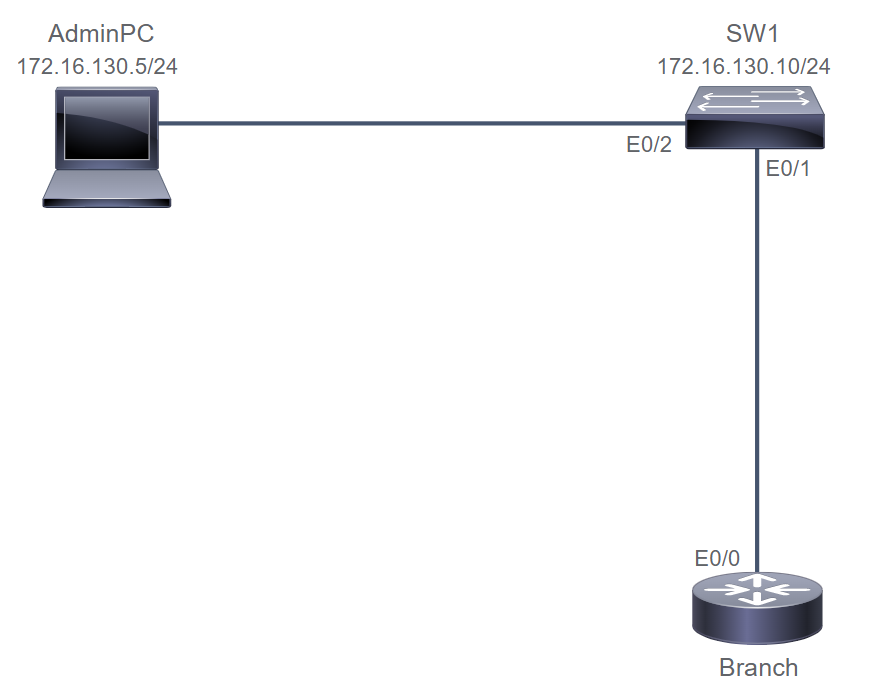
Router# conf t
Router(config)# hostname Branch
Branch(config)# int eth0/0
Branch(config-if)# desc Link to SW1

Branch(config-if)# int e0/0
Branch(config-if)# ip addr 172.16.130.3 255.255.255.0
Branch(config-if)# no shut

Branch# sh ip int e0/0
Branch# ping 172.16.130.10

Branch(config)# int loopback0
Branch(config-if)# ip address 172.16.2.2 255.255.255.255
Branch# sh ip int loopback0
Branch# ping 172.16.130.5 source loopback0

SW1(config)# int Eth0/1
SW1(config-if) desc Link to Branch
SW1# sh run int e0/1
11. Exploring the Packet Delivery Process
Address Resolution Protocol
- ARP provides two essential services:
- Address Resolution: Mapping IPv4 addresses to MAC Addresses on a network
- Caching: locally storing MAC Addresses that are learned via ARP
- ARP sends a broadcast message to all devices on the local network use Source Destination IPv4 Address and receives the reply frame which contain MAC addresses
- ARP is layer2 protocol and limited to the local LAN. If the destination devices are not on the same subnet, the ARP use default gateway MAC address.
C:\> arp -a
C:\> arp -a -N 10.99.11.74

R1# show ip arp
Protocol    Address   Age (min)   Hardware Addr   Type    Interface
Internet    10.1.1.1  5           001b.d59c.3427  ARPA    GigE0/0

R1# show arp
Protocol    Address   Age (min)   Hardware Addr   Type    Interface
Internet    10.1.1.1  5           001b.d59c.3427  ARPA    GigE0/0
Configure Default Gateway
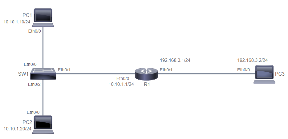
  PC1# sh arp
  PC1# ping 10.10.1.20
  PC1# ping 10.10.1.1
  PC1# ping 10.10.1.2
  PC1# sh arp
  PC1# ping 192.168.3.2
  PC1# sh arp

  PC1# conf t
  PC1(config)# ip default-gateway 10.10.1.1
  PC1(config)# do sh ip route
  PC1(config)# end

  PC1# clear ip arp 192.168.3.2
  PC1# sh arp
  PC1# ping 192.168.3.2
  PC1# sh arp --> now the ARP for 192.168.3.2 is not appear
Host-to-Host Packet Delivery (14 steps)
- Host A send a Data use UDP to 192.168.4.2
- UDP prepare header and put source destination IP address to 192.168.4.2
- Host A analyze the destination address on different network, so layer3 forwarded to default gateway.
- Because layer2 don’t have mapping MAC Address of the default gateway, packet must placed on parking lot, until it has the MAC Address of the default gateway.
- Layer2 at Host A use ARP process to map the default gateway address and send broadcast ARP request to default gateway.
- Host A sends a ARP request. The router receives it and add the host to router ARP table.
- Router sends ARP reply with its information to host MAC address.
- Host A receives an ARP reply and add to ARP table. So, Layer2 have the MAC address of the default gateway
- Pending packet, now Layer2 can send it to default gateway MAC address
- Layer2 router receive the packet and found the destination is not to its router. So, it need to be forwarded by Layer3 to it’s destination IPv4 Address.
- Layer3 have the destination IPv4 and forward the packet directly to the host and Layer2 send the packet because it’s directly connected.
- Router don’t have ARP Mapping to destination IP, and Layer2 ask information as same way as the hosts A.
- Router got ARP Reply from destination IP and populate its local ARP table, and starts the paket-forwarding process.
- The frame is forwarded to the destination.
Role of switch in Packet Delivery
- Switch just received a frame from a host that is not in switch MAC table, then add it to the table
- Because the destination address of the frame is broadcast, Switch flood the frame out on all ports
- Router reply the ARP request and Switch learns the port mapping for the router MAC address.
- The destination MAC address now found in Switch and can be forwarded the frame out on port Fa0/1.
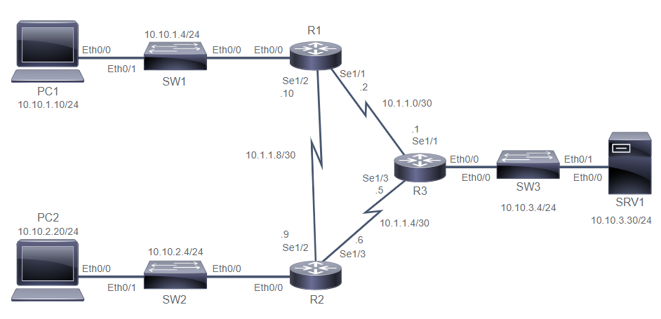
Explore packet forwarding
  PC1# ping 10.10.3.30
  PC1# traceroute 10.10.3.30
  1 10.10.1.1
  2 10.1.1.1
  3 10.10.3.30

  PC1# sh int e0/0 | i addr
  MAC aabb.cc01.8900
  IP 10.10.1.10/24

  R1# sh int e0/0 | i addr
  MAC aabb.cc01.8600
  IP 10.10.1.1/24

  R1# sh int e0/1 | i addr
  MAC aabb.cc01.8610
  IP 10.10.1.2/30

  R2# sh int e0/0 | i addr
  MAC aabb.cc01.8800
  IP 10.10.3.1/24

  R2# sh int e0/1 | i addr
  MAC aabb.cc01.8810
  IP 10.10.1.1/30

  SRV1# sh int e0/0 | i addr
  MAC aabb.cc01.a200
  IP 10.10.3.30/24

  PC1# sh ip arp
  PC1# debug arp
  PC1# conf t
  PC1(config)# int e0/0
  PC1(config-if)# shut
  PC1(config-if)# no shut

  PC1(config-if)# do ping 10.10.3.30
  PC1(config-if)# do sh arp
  PC1# undebug all

  R1# sh arp
  R3# sh arp
  SW1# sh mac address-table dynamic
  SW1# clear mac address-table
  SW1# sh mac address-table dynamic
12. Troubleshooting a Simple Network
Common troubleshooting Method:
- Top-Down Method: each layer depends on the underlying layers for its operation, troubleshoot from applcation layer to the last physical layer.
- Bottom-up Method: work from physical layer to the application layer. disadventage of this is when analyze a large network.
- Divide-and-conquer Method: Start in the middle of the OSI layer then go up or down.
- Follow-the-path method: Determine the part that packets follow through the network. Isolate the problem by tracing the path of the packets.
- Swap Component Method: Move components physically and observe if the problem moves withthe components or not.
- Perform comparison method: Compare devices or processes of the network that are operating correctly to devices or processes that are not operating as expected.
Troubleshooting Tools:
-
Logging: you can chronologically see the events that have triggered logging events. Level numbered from 0 to 7 (emeergency, alert, critical, error, warning, notification, informational, debugging).
R1# show logging R1# terminal monitor --> enable logging to terminal sessions -
Internet Control Message Protocol (ICMP): ICMP messages are typically used for diagnostic or control purposes or generated in response to errors in IP operations.
PC1# traceroute xxxx PC1# tracert xxxx --> for windows PC1# ping xxxx -
Verification of End-to-End IPv4 Connectivity:
PC1# ping xxxx PC1# traceroute xxxx PC1# telnet xxxx PC1# ssh xxxx PC1# show ip arp PC1# show arp PC1# show ip interface brief PC11# ipconfig /all -
Using
Ping: use ICMP echo messages to determine:- Wheater remote host is active or not
- The round-trip time (RTT) in communicating with the host
- Packet loss
-
Using
traceroute(Cisco IOS) ortracert(Microsoft Windows): is used to test the path that pakcets take through the network.R1# traceroute 10.10.50.2 source Loopback0 --> test connectivity from specified source -
Using
TelnetandSSH: telnet use port 23 and ssh use port 22. telnet used as a troubleshooting tool to check transport layer functionality and shouldn’t use in a production environment. SSH is used as a secure access method.R1# telnet 10.10.50.2 80 R1# ssh userA@10.10.50.2:/ -
Verify ARP Table:
R1# show ip arp --> display arp table R1# show arp --> display arp table R1# arp -a --> display IPv4-to-MAC address on windows -
Verify IPv4 Address information: displays the IP address, subnet mask, and gateway for all physical and virtual network adapters.
  PC1# ipconfig /all
  R1# show ip int brief
Common Switch Media Issues:
- Copper media issues have several possible sources:
- Wiring become demaged
- New EMI sources are introduced
- Traffic patterns change
- New equipment is installed
- Fiber Media issue have these possible losses:
- Microbend and Macrobend losses
- Troubleshooting Media issues workflow
- Use
bashow intto check interface status. - Use
bashow intto check excessive noise (see increase error counters) - Use
bashow intto check for excessive collisions (verify duplex settings on both)
- Use
Common Switch port issues:
-
Duplex and Speed-Related Issues:
- One end is set to Full Duplex, and another set to Half Duplex
- One end is set to Full Duplex, and another set to Autonegotiation (if auto fails, then revert to half duplex)
- One end is set to Half Duplex, and another set to Autonegotiation
-
Troubleshooting process for duplex and speed related issues:
- Guideline for duplex configuration
- P2P ethernet should always run in full-duplex mode, half-duplex is not common anymore
- Autonegotiation is recomended on ports that are connected to non-critical endpoints
- Manually set the speed and duplex for critical endpoints
- Troubleshoot general process:
- Use
bashow intto check speed mismatch and then set it to the same value - Use
bashow intto check duplex mismatch and then set it full duplex for recommended value.R1# sh int Fa0/1 Full-Duplex, 100Mb/s, media type is 10/100BaseTX R1(config-if)# duplex full/half/auto R1(config-if)# speed 100 R1# write
- Use
- Guideline for duplex configuration
-
Troubleshooting physical connectivity issues:
-
bashow int GigE0/1to display following important statistics:- Input Queue drops: if too many input drop, probably CPU can’t process packets in time
- Output queue drops: packet dropped due to congestion on the interface. If it consistent output drop, you need to implement advanced queuing mechanism.
- Input Errors: High number of CRC errors could indicate cabling problems, interface hardware problem, or duplex mismatch
- Output Errors: indicate errors such as collisions, during the transmission of a frame.
-
Troubleshooting switch Media and port issues:
SW1# ping 10.10.1.20 --> PC2
Not working
SW1# sh int status
all connected and looks good
SW1# sh cdp nei
all good and okey

SW2# sh int status
Et0/2   Link to PC2   disabled    1   auto    auto unkonwn
SW2# sh int e0/2
Eth0/2 is administratively down
SW2# sh run int e0/2
      shutdown
SW2# conf t
SW2(config)# int e0/2
SW2(config-int)# no shut
SW2(config-int)# do sh spann vlan 1
Et0/2   Desg  LRN   100   128.3   Shr --> still learning, wait a moment
SW2(config-int)# do sh spann vlan 1
Et0/2   Desg  FWD   100   128.3   Shr --> now it is forwarding
SW2# sh int status
SW2# write

SW1# ping 10.10.1.20
working
Troubleshooting port Duplex
SW2# show logging
Syslog logging: enabled (0 messages dropped, 0 messages rate-limited, 0 flushes, 0 overruns, xml disabled, filtering disabled)
No Active Message Discriminator.
No Inactive Message Discriminator.
    Console logging: level debugging, 15 messages logged, xml disabled,
                     filtering disabled
    Monitor logging: level debugging, 0 messages logged, xml disabled,
                     filtering disabled
    Buffer logging:  level debugging, 15 messages logged, xml disabled,
                    filtering disabled
    Exception Logging: size (4096 bytes)
    Count and timestamp logging messages: disabled
    Persistent logging: disabled
    Trap logging: level informational, 18 message lines logged
        Logging Source-Interface:       VRF Name:
<... output omitted ...>

SW2#
%CDP-4-DUPLEX_MISMATCH: duplex mismatch discovered on FastEthernet0/13 (not full duplex), with R1 FastEthernet0/0 (full duplex).
SW2#

SW2# show interfaces FastEthernet0/13
FastEthernet0/13 is up, line protocol is up (connected)
  Hardware is Fast Ethernet, address is 000b.5fe5.81cd (bia 000b.5fe5.81cd)
  MTU 1500 bytes, BW 100000 Kbit, DLY 100 usec,
     reliability 255/255, txload 1/255, rxload 1/255
  Encapsulation ARPA, loopback not set
  Keepalive set (10 sec)
  Half-duplex, Auto-speed, media type is 100BaseTX
  input flow-control is unsupported output flow-control is unsupported
  ARP type: ARPA, ARP Timeout 04:00:00
<… output omitted …>

SW2# show ip interface brief | include 0/13
FastEthernet0/13           unassigned      YES unset  up                  up

SW2# configure terminal
Enter configuration commands, one per line.  End with CNTL/Z.
SW2(config)# interface FastEthernet 0/13
SW2(config-if)# duplex full

SW2(config-if)# do copy running-config startup-config
Destination filename [startup-config]? <Enter>
Building configuration...
[OK]
Troubleshooting steps
- Verify the host IPv4 address and subnet mask
PC1# ipconfig IPv4 address : 172.16.10.2 Subnet Mask : 255.255.255.0 Default Gateway : 172.16.10.1 - Ping the loopback address
PC1# ping 127.0.0.1 - Ping the IPv4 address of the local interface
PC1# ping 172.16.10.2 - Ping the default gateway
PC1# ping 172.16.10.1 - Ping the remote server
PC1# ping 172.16.20.2 - Check the default gateway
 PC1# route print --> for windows
 PC1# sh ip int bri
 PC1# sh ip route
 PC1# sh run
13. Introducing Basic IPv6
IPv6 Features:
-
Larger address space: expanded address space
- Provides improved global reachability and flexibility
- A better aggregation of IP prefixes
- a host can have multiple IP addresses over one physical upstream link
- Autoconfigure is available
- More plug and play option for more devices
- Simplified mechanism for address renumbering and modification
- Simpler Header: streamlined fixed header structures
- Security and Mobility: IPsec is allowing the IPv6 networks to secure and mobility enables mobile devices to move around in networks without breaks in established network connections
- Transition richness: rich set of tools to aid in transitioning networks from IPv4 to IPv6-dominant networks.
IPv6 Address Types
-
Unicast: used in a one-to-one context
-
Global-Unicast: generally assigned in a hierarchical manner by ISPs and it’s routable and reachable across the internet. 1-48: Provider/Global routing prefix(RIR-ISP-site), 48-64: Subnet ID(Home Site-Subnet) for own local addressing, 64-128: Interface ID (must be unique for each host). Example
2001:0db8:bbbb:cccc:0987:65ff:fe01:2345. -
Link-Local Unicast: smaller scope than site-local addresses and can be used for communicate or troubleshoot between local network. Only for local communication on particular physical network segment and router not forward the packets. Every device must have link-local address and it’s automatically configured. Example
fe80::/10. -
Unique Local Unicast: same with private IPv4 that used for local communication, intersite VPN, and not inteded to translated to a global unicast address. It’s not routable on the internet without IPv6 NAT but routable in site or site to site. Example
fc00:aaaa:bbbb:cccc:0987:65ff:fe01:2345–> fc00:Global-ID(40bits):Subnet-ID(16bits):Interface-ID(64bits).
-
Global-Unicast: generally assigned in a hierarchical manner by ISPs and it’s routable and reachable across the internet. 1-48: Provider/Global routing prefix(RIR-ISP-site), 48-64: Subnet ID(Home Site-Subnet) for own local addressing, 64-128: Interface ID (must be unique for each host). Example
-
Multicast: identifies a group of interfaces, it replace the broadcast addresses. Example:
ff00::/8first 8bits areff, followed by 4bits forflag, 4bits for Scopefield, and 112bits represent thegroup ID. -
Anycast: is unicast address assigned to an interface on more than one node, when packet sent to anycast address, it’s routed to the nearest interface. example:
2001:db8:10f:1::/64 - Reserved: reserve for present or future, lowest address within each subnet is reserved as the subnet-router anycast address, the 128 highest addresses within each subnet prefix are reserved for use as anycast address.
IPv6 Scope and Prefix
| Address | Value | Description |
|---|---|---|
| Global-cast | 2000::/3 | used in public network (IANA) |
| Link-local | fe80::/10 | auto configured on an physical interface (required) |
| unique-local | fc00::/7 | private address used for local communications in scope for entire site or organization |
| loopback | ::1 | used for local testing function |
| unspecified | :: | “unknown” address, used in the source address |
Comparison of IPv4 and IPv6:
- Reason to remove several fields from IPv4:
- Internet header length field is no longer required, IPv6 header is fixed at 40 octets.
- Router no longer proceed fragmentation, and IPv6 host responsible for MTU discovery and if needed do the fragmentation.
- Most data link layer technologies already perform checksum and error control.
- IPv6 Header contains 8 fields:
- Version: 4bits contains number 6 for IPv6
- Traffic Class: 8bits uses to mark the priority of outbound packets
- Flow Label: 20bits used to mark individual traffic flows with unique values.
- Payload Length: describes the length of the payload only, not the entire packets.
- Next Header: determines the type of information that follows the basic IPv6 header.
- Hop Limit: specifies the max number of hops that IPv6 packet can take.
- Source Address: 128bits identifies the source of the packet
- Destination Address: 128bits identifies the destination of the packet
- Transitioning IPv6 to IPv4:
- Dual-stack network IPv4 & IPv6 are fully deployed across the infrastructure
- Tunneling overlay network that tunnels one protocols over the other by encapsulating packet to the network.
- Transitioning facilitate communication between two address type hosts and network by performing header and address translation
Internet Control Message Protocol (ICMP) v6
-
Destination Unreachable type field
1 -
Echo Request used for ping, type field
128&129 -
Router used to find router, type field
133&134 -
Neighbor used to discover neighbor device, type field
135&136
Stateless Address Autoconfiguration(SLAAC)
- Alternative to DHCP v6 to automatically populate the IPv6 Address.
- Router advertisement packet:
- ICMP type: 134
- Source: Router link-local address (
fe80) - Destination:
ff02::1(all-nodes multicast) - Data:
ff02::2(Options, Prefix, lifetime, autoconfiguration flag)
- Router soliciation packet:
- ICMP type: 133
- Source: unspecified address (
::) (don’t have any IP) - Destination:
ff02::2(all-router multicast adddress)
Branch(config-if)# ipv6 addr autoconfig [default]R2# sh ipv6 int br Eth0/2 [up/up] unassigned R2# conf t R2(config)# int e0/2 R2(config-if)# ipv6 add 2001:123:456:10::1/64 R2(config-if)# do sh ipv6 int br Eth0/2 [up/up] fe80::a8bb:ccff:fe01:d520 2001:123:456:10::1 R2# sh ipv6 route C 2001:123:456:10::/64 [0/0] via eth0/2, directly connected L 2001:123:456:10::1/128 [0/0] via eth0/2, directly connected R2# sh run ipv6 unicast-routing - Router advertisement packet:
- Several way to asiign an IPv6 to device:
-
Static Assignment using a manual interface ID: Manually assign both the prefix (network) and interface ID (host) portions of IPv6.
R1(config)# int E0/0 R1(config-if)# ipv6 addr 2001:db8:2222:7272::72/64 R1(config-if)# ipv6 addr fe80::1 link-local -
Static Assignment using an EUI-64 interface ID: configure the prefix (network) portion of the IPv6 address and derive the interface ID (host) portion from the MAC address of the device, which is known as the EUI-64 interace ID.
R1(config)# int E0/0 R1(config-if)# ipv6 addr 2001:0db8:0:1::/64 eui-64 -
Stateless Address autoconfiguration (SLAAC): a mechanism that automatically configures the IPv6 address of a node. SLAAC use neighbor discovery mechanisms to find routers and dynamically assign IPv6 Addresses based on the prefix advertised by the routers. it’s enable plug-and-play networking of devices to help reduce administration overhead.
R1(config)# int E0/0 R1(config-if)# ipv6 addr autoconfig [default] - Stateful DHCPv6: It offers the capability of automatic allocation of reusable network addresses and additional configuration flexibility. Stateful means DHCP server is responsible for record and assigning the IPv6 to the client.
- Stateless DHCPv6: The device gets its IPv6 address and default gateway using SLAAC. but, device then sends a query to a DHCPv6 server for other information such as domain names, DNS servers, and other client relevant information.
-
Static Assignment using a manual interface ID: Manually assign both the prefix (network) and interface ID (host) portions of IPv6.
Configuring basic IPv6 Connectivity
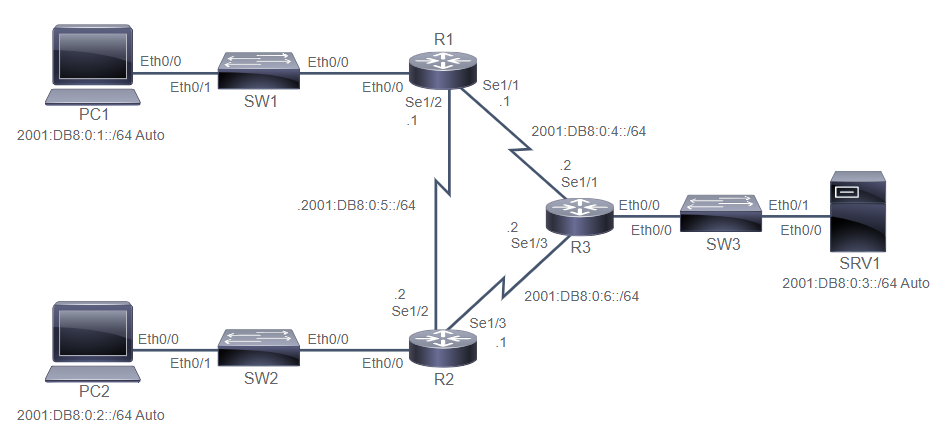
R1# conf t
R1(config)# ipv6 unicast-routing
R1(config)# do sh ipv6 ro

R1(config)# int s1/2
R1(config-if)# ipv6 add 2001:db8:0:5::1/64
R1(config-if)# do ping 2001:db8:0:5::2
R1(config-if)# int e0/0
R1(config-if)# ipv6 add 2001:db8:0:1::1/64
R1(config-if)# int s1/1
R1(config-if)# ipv6 add 2001:db8:0:4::1/64

R1(config-if)# do sh ipv6 int br
R1(config-if)# do sh ipv6 int e0/0

R3# conf t
R3(config)# ipv6 unicast-routing
R3(config)# do sh ipv6 ro

R3(config)# int s1/1
R3(config-if)# ipv6 add 2001:db8:0:4::2/64
R3(config-if)# int s1/3
R3(config-if)# ipv6 add 2001:db8:0:6::2/64
R3(config-if)# do ping 2001:db8:0:6::1  --> router2
R3(config-if)# do ping 2001:db8:0:4::1  --> router1
R1(config-if)# int e0/0
R1(config-if)# ipv6 add 2001:db8:0:3::2/64

R3(config-if)# do sh ipv6 int br
R3(config-if)# do sh ipv6 int e0/0
14. Configuring Static Routing
Routing operation:
- Identify the destination of the packet
- Identify the sources of routing information
- Identify route paths
- Select best route paths
- Maintain and verify routing information
Static and Dynamic Routing Comparison:
-
Static Routing:
- Manually configure and update whenever the topology changed.
- Router behavior can be precisely controlled
-
Dynamic Routing:
- automatically adjusts when topology changed
- learn and maintain routes and discover new networks by sharing routing table information
When to Use Static Routing:
- Use static route in this situation:
- In a simple network that requires only simple routing
- In hub-and-spoke network topology
- Common use is a default static route
- When you want to create a quick and hoc route
- Advantages of using static routes:
- Conserving router resources: such as CPU and network bandwadth
- Simple: to configure in a small network
- Secure: Define static routes to control data transmission path
- Disaventage of using static routes:
- Scalability: appropriate for fewer than four or five routers
- Accuracy: Not having accurate knowledge of your network
- High Maintenance: when any changes on topology
IPv4 Static Route Configuration:
  R1(config)# ip route 172.16.1.0 255.255.255.0 172.16.2.1
  R1(config)# ip route 172.16.1.0 255.255.255.0 s0/0/0
  R1(config)# ip route 172.16.1.0 255.255.255.0 172.16.2.1 10

  R1(config)# ip route 0.0.0.0 0.0.0.0 172.16.2.2
  R1(config)# ip route 0.0.0.0 0.0.0.0 s0/0/1
Verify Static and Dynamic Route
  RouterA# show ip route static
  Gateway of last resort is not set
    S 172.16.1.0/24 [1/0] via 172.16.2.1

  RouterB(config)# ip route 0.0.0.0 0.0.0.0 Serial0/0/1
  RouterB# show ip route static
  Gateway of last resort is 0.0.0.0 to network 0.0.0.0
    S* 0.0.0.0/0 is directly connected, Serial0/0/1

  RouterB# show ip route static
  Gateway of last resort is 172.16.2.2 to network 0.0.0.0
    S* 0.0.0.0/0 [1/0] via 172.16.2.2
Configure and verify IPv4 Static Routes
 Verify Device Reachability
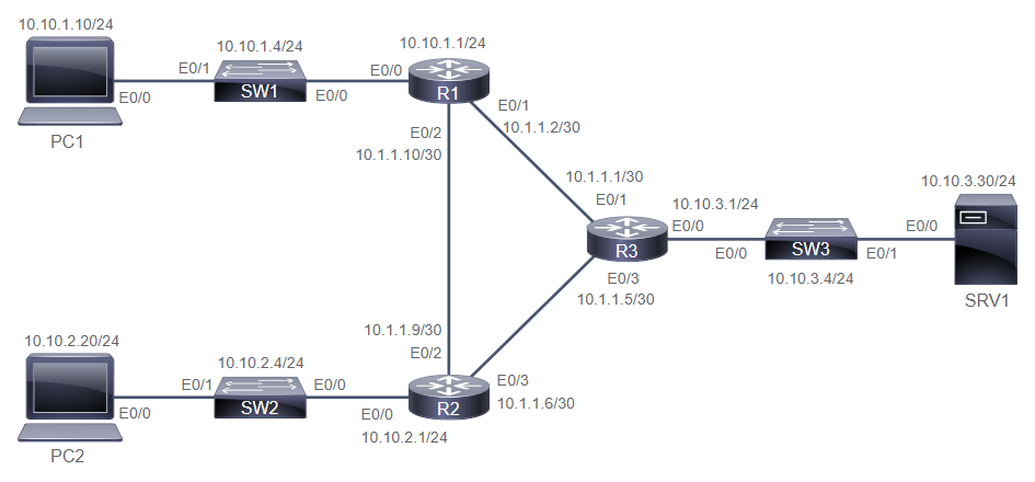
  PC1# ping 10.10.1.4 --> success
  PC1# ping 10.10.1.1 --> success

  PC1# show ip route
  Default gateway is 10.10.1.1
  Host               Gateway           Last Use    Total Uses  Interface
  ICMP redirect cache is empty

  PC1# ping 10.1.1.2 --> success
  PC1# ping 10.1.1.10 --> success
  PC1# ping 10.1.1.9 --> failed
Configure and Verify Static Routes
  R1# configure terminal
  R1(config)# ip route 10.10.2.0 255.255.255.0 10.1.1.9
  R1(config)# ip route 10.10.3.0 255.255.255.0 10.1.1.1
  R1(config)# end

  R2# configure terminal
  R2(config)# ip route 10.10.1.0 255.255.255.0 10.1.1.10
  R2(config)# ip route 10.10.3.0 255.255.255.0 10.1.1.5
  R2(config)# end

  PC1# ping 10.10.2.20 --> failed
  PC1# ping 10.10.3.30 --> failed
  PC1# ping 10.1.1.6 --> failed

  R1# configure terminal
  R1(config)# ip route 10.1.1.4 255.255.255.252 10.1.1.9
  R1(config)# end

  R2# configure terminal
  R2(config)# ip route 10.1.1.0 255.255.255.252 10.1.1.10
  R2(config)# end

  R3# configure terminal
  R3(config)# ip route 10.10.1.0 255.255.255.0 10.1.1.2
  R3(config)# ip route 10.10.2.0 255.255.255.0 10.1.1.6
  R3(config)# ip route 10.1.1.8 255.255.255.252 10.1.1.2
  R3(config)# end

  R1# show ip route
  Gateway of last resort is not set
        10.0.0.0/8 is variably subnetted, 9 subnets, 3 masks
  C        10.1.1.0/30 is directly connected, Serial1/1
  L        10.1.1.2/32 is directly connected, Serial1/1
  S        10.1.1.4/30 [1/0] via 10.1.1.9
  C        10.1.1.8/30 is directly connected, Serial1/2
  L        10.1.1.10/32 is directly connected, Serial1/2
  C        10.10.1.0/24 is directly connected, Ethernet0/0
  L        10.10.1.1/32 is directly connected, Ethernet0/0
  S        10.10.2.0/24 [1/0] via 10.1.1.9
  S        10.10.3.0/24 [1/0] via 10.1.1.1

  R1# show running-config | include route
  ip route 10.1.1.4 255.255.255.252 10.1.1.9
  ip route 10.10.2.0 255.255.255.0 10.1.1.9
  ip route 10.10.3.0 255.255.255.0 10.1.1.1

  PC1# ping 10.10.2.20 --> success
  PC1# ping 10.10.3.30 --> success
  PC1# ping 10.1.1.6 --> success
  PC1# ping 10.1.1.5 --> success
Demonstrate Static Route Drawbacks
  PC1# traceroute 10.10.2.20
  Type escape sequence to abort.
  Tracing the route to 10.10.2.20
  VRF info: (vrf in name/id, vrf out name/id)
    1 10.10.1.1 1 msec 1 msec 1 msec
    2 10.1.1.9 1 msec 0 msec 1 msec
    3 10.10.2.20 2 msec *  2 msec

  PC1# traceroute 10.10.3.30
  Type escape sequence to abort.
  Tracing the route to 10.10.3.30
  VRF info: (vrf in name/id, vrf out name/id)
    1 10.10.1.1 1 msec 1 msec 1 msec
    2 10.1.1.1 1 msec 0 msec 0 msec
    3 10.10.3.30 1 msec *  1 msec

  R3# configure terminal
  R3(config)# interface Serial 1/1
  R3(config-if)# shutdown
  R3(config-if)# end
  R3#
  *Oct 15 07:04:28.078: %SYS-5-CONFIG_I: Configured from console by console
  R3#
  *Oct 15 07:04:29.292: %LINK-5-CHANGED: Interface Serial1/1, changed state to administratively down
  *Oct 15 07:04:30.296: %LINEPROTO-5-UPDOWN: Line protocol on Interface Serial1/1, changed state to down

  R1#
  *Oct 15 07:04:57.975: %LINEPROTO-5-UPDOWN: Line protocol on Interface Serial1/1, changed state to down

  R1# show ip interface brief
  Interface                  IP-Address      OK? Method Status                Protocol
  Ethernet0/0                10.10.1.1       YES NVRAM  up                    up
  Ethernet0/1                unassigned      YES NVRAM  administratively down down
  Ethernet0/2                unassigned      YES NVRAM  administratively down down
  Ethernet0/3                unassigned      YES NVRAM  administratively down down
  Serial1/0                  unassigned      YES NVRAM  administratively down down
  Serial1/1                  10.1.1.2        YES NVRAM  up                    down
  Serial1/2                  10.1.1.10       YES NVRAM  up                    up
  Serial1/3                  unassigned      YES NVRAM  administratively down down

  R1# show ip route
  Gateway of last resort is not set
        10.0.0.0/8 is variably subnetted, 6 subnets, 3 masks
  S        10.1.1.4/30 [1/0] via 10.1.1.9
  C        10.1.1.8/30 is directly connected, Serial1/2
  L        10.1.1.10/32 is directly connected, Serial1/2
  C        10.10.1.0/24 is directly connected, Ethernet0/0
  L        10.10.1.1/32 is directly connected, Ethernet0/0
  S        10.10.2.0/24 [1/0] via 10.1.1.9

  PC1# ping 10.10.3.30 --> failed
  PC1# traceroute 10.10.3.30
  Tracing the route to 10.10.3.30
  VRF info: (vrf in name/id, vrf out name/id)
    1 10.10.1.1 1 msec 1 msec 0 msec
    2 10.10.1.1 !H  *  !H

  R3# configure terminal
  Enter configuration commands, one per line.  End with CNTL/Z.
  R3(config)# interface Serial 1/1
  R3(config-if)# no shutdown
  R3(config-if)# end
  R3#
  *Oct 15 07:13:12.022: %LINK-3-UPDOWN: Interface Serial1/1, changed state to up
  R3#
  *Oct 15 07:13:12.747: %SYS-5-CONFIG_I: Configured from console by console
  *Oct 15 07:13:13.027: %LINEPROTO-5-UPDOWN: Line protocol on Interface Serial1/1, changed state to up

  R1#
  *Oct 15 07:13:18.148: %LINEPROTO-5-UPDOWN: Line protocol on Interface Serial1/1, changed state to up

  PC1# ping 10.10.3.30 --> success
  PC1# traceroute 10.10.3.30
  Tracing the route to 10.10.3.30
  VRF info: (vrf in name/id, vrf out name/id)
    1 10.10.1.1 1 msec 1 msec 1 msec
    2 10.1.1.1 10 msec 10 msec 9 msec
    3 10.10.3.30 11 msec *  9 msec
Configure and Verify the Backup Static Route
  R1# configure terminal
  R1(config)# ip route 10.10.2.0 255.255.255.0 10.1.1.1 2
  R1(config)# ip route 10.10.3.0 255.255.255.0 10.1.1.9 2
  R1(config)# ip route 10.1.1.4 255.255.255.252 10.1.1.1 2
  R1(config)# end
  R1# show running-config | include route
  ip route 10.1.1.4 255.255.255.252 10.1.1.9
  ip route 10.1.1.4 255.255.255.252 10.1.1.1 2
  ip route 10.10.2.0 255.255.255.0 10.1.1.9
  ip route 10.10.2.0 255.255.255.0 10.1.1.1 2
  ip route 10.10.3.0 255.255.255.0 10.1.1.1
  ip route 10.10.3.0 255.255.255.0 10.1.1.9 2

  R1# show ip route static
  Gateway of last resort is not set
        10.0.0.0/8 is variably subnetted, 9 subnets, 3 masks
  S        10.1.1.4/30 [1/0] via 10.1.1.9
  S        10.10.2.0/24 [1/0] via 10.1.1.9
  S        10.10.3.0/24 [1/0] via 10.1.1.1

  R2# configure terminal
  R2(config)# ip route 10.10.1.0 255.255.255.0 10.1.1.5 2
  R2(config)# ip route 10.10.3.0 255.255.255.0 10.1.1.10 2
  R2(config)# ip route 10.1.1.0 255.255.255.252 10.1.1.5 2
  R2(config)# end

  R3# configure terminal
  R3(config)# ip route 10.10.1.0 255.255.255.0 10.1.1.6 2
  R3(config)# ip route 10.10.2.0 255.255.255.0 10.1.1.2 2
  R3(config)# ip route 10.1.1.8 255.255.255.252 10.1.1.6 2
  R3(config)# end

  R3# configure terminal
  R3(config)# interface Serial 1/1
  R3(config-if)# shutdown
  R3(config-if)# end
  R3#
  *Oct 15 07:29:34.297: %SYS-5-CONFIG_I: Configured from console by console
  *Oct 15 07:29:35.080: %LINK-5-CHANGED: Interface Serial1/1, changed state to administratively down
  R3#
  *Oct 15 07:29:36.084: %LINEPROTO-5-UPDOWN: Line protocol on Interface Serial1/1, changed state to down

  R1#
  *Oct 15 07:29:58.519: %LINEPROTO-5-UPDOWN: Line protocol on Interface Serial1/1, changed state to down

  R1# show ip route
  Gateway of last resort is not set
        10.0.0.0/8 is variably subnetted, 7 subnets, 3 masks
  S        10.1.1.4/30 [1/0] via 10.1.1.9
  C        10.1.1.8/30 is directly connected, Serial1/2
  L        10.1.1.10/32 is directly connected, Serial1/2
  C        10.10.1.0/24 is directly connected, Ethernet0/0
  L        10.10.1.1/32 is directly connected, Ethernet0/0
  S        10.10.2.0/24 [1/0] via 10.1.1.9
  S        10.10.3.0/24 [2/0] via 10.1.1.9

  PC1# ping 10.10.3.30 --> success

  PC1# traceroute 10.10.3.30
  Type escape sequence to abort.
  Tracing the route to 10.10.3.30
  VRF info: (vrf in name/id, vrf out name/id)
    1 10.10.1.1 1 msec 0 msec 1 msec
    2 10.1.1.9 9 msec 9 msec 9 msec
    3 10.1.1.5 17 msec 18 msec 17 msec
    4 10.10.3.30 15 msec *  18 msec

  R3# configure terminal
  R3(config)# interface Serial 1/1
  R3(config-if)# no shutdown
  R3(config-if)# end
  R3#
  *Oct 15 07:34:30.570: %SYS-5-CONFIG_I: Configured from console by console
  R3#
  *Oct 15 07:34:30.968: %LINK-3-UPDOWN: Interface Serial1/1, changed state to up
  *Oct 15 07:34:31.972: %LINEPROTO-5-UPDOWN: Line protocol on Interface Serial1/1, changed state to up

  R1#
  *Oct 15 07:34:38.628: %LINEPROTO-5-UPDOWN: Line protocol on Interface Serial1/1, changed state to up

  R1# show ip route
  Gateway of last resort is not set
        10.0.0.0/8 is variably subnetted, 9 subnets, 3 masks
  C        10.1.1.0/30 is directly connected, Serial1/1
  L        10.1.1.2/32 is directly connected, Serial1/1
  S        10.1.1.4/30 [1/0] via 10.1.1.9
  C        10.1.1.8/30 is directly connected, Serial1/2
  L        10.1.1.10/32 is directly connected, Serial1/2
  C        10.10.1.0/24 is directly connected, Ethernet0/0
  L        10.10.1.1/32 is directly connected, Ethernet0/0
  S        10.10.2.0/24 [1/0] via 10.1.1.9
  S        10.10.3.0/24 [1/0] via 10.1.1.1
Configure and Verify the Default Route
  R1# configure terminal
  R1(config)# no ip route 10.1.1.4 255.255.255.252 10.1.1.9
  R1(config)# no ip route 10.1.1.4 255.255.255.252 10.1.1.1 2
  R1(config)# no ip route 10.10.2.0 255.255.255.0 10.1.1.9
  R1(config)# no ip route 10.10.2.0 255.255.255.0 10.1.1.1 2
  R1(config)# no ip route 10.10.3.0 255.255.255.0 10.1.1.1
  R1(config)# no ip route 10.10.3.0 255.255.255.0 10.1.1.9 2
  R1(config)# end

  R1# show running-config | include route
  R1# show ip route
  Gateway of last resort is not set
        10.0.0.0/8 is variably subnetted, 6 subnets, 3 masks
  C        10.1.1.0/30 is directly connected, Serial1/1
  L        10.1.1.2/32 is directly connected, Serial1/1
  C        10.1.1.8/30 is directly connected, Serial1/2
  L        10.1.1.10/32 is directly connected, Serial1/2
  C        10.10.1.0/24 is directly connected, Ethernet0/0
  L        10.10.1.1/32 is directly connected, Ethernet0/0

  R1# configure terminal
  R1(config)# ip route 0.0.0.0 0.0.0.0 10.1.1.1
  R1(config)# end
  R1# show running-config | include route
  ip route 0.0.0.0 0.0.0.0 10.1.1.1

  R1# show ip route
  Gateway of last resort is 10.1.1.1 to network 0.0.0.0
  S*    0.0.0.0/0 [1/0] via 10.1.1.1
        10.0.0.0/8 is variably subnetted, 6 subnets, 3 masks
  C        10.1.1.0/30 is directly connected, Serial1/1
  L        10.1.1.2/32 is directly connected, Serial1/1
  C        10.1.1.8/30 is directly connected, Serial1/2
  L        10.1.1.10/32 is directly connected, Serial1/2
  C        10.10.1.0/24 is directly connected, Ethernet0/0
  L        10.10.1.1/32 is directly connected, Ethernet0/0

  PC1# ping 10.10.3.30 --> success
  PC1# ping 10.10.2.20 --> success
  PC1# ping 10.1.1.9 --> success

  PC1# traceroute 10.10.2.20
  Tracing the route to 10.10.2.20
  VRF info: (vrf in name/id, vrf out name/id)
    1 10.10.1.1 1 msec 0 msec 1 msec
    2 10.1.1.1 9 msec 5 msec 9 msec
    3 10.1.1.6 13 msec 13 msec 13 msec
    4 10.10.2.20 14 msec *  15 msec

  PC1# traceroute 10.1.1.9
  Tracing the route to 10.1.1.9
  VRF info: (vrf in name/id, vrf out name/id)
    1 10.10.1.1 0 msec 0 msec 0 msec
    2 10.1.1.9 11 msec *  9 msec

  PC2# ping 10.10.1.10 --> success
  PC2# traceroute 10.10.1.10
  Tracing the route to 10.10.1.10
  VRF info: (vrf in name/id, vrf out name/id)
    1 10.10.2.1 1 msec 0 msec 0 msec
    2 10.1.1.10 13 msec 14 msec 13 msec
    3 10.10.1.10 15 msec *  13 msec
Configure IPv6 Static Route
  Router# configure terminal
  Router(config)# ipv6 unicast-routing
  Router(config)# ipv6 route 2001:0db8:beef::/32 fa1/0 fe80::2 --> only when use link-local next hop address
  Router(config)# ipv6 route 2001:0db8:beef::/32 2001:0db8:feed::1

  HQ(config)# ipv6 route 2001:db8:a01::/48 2001:db8:d1a5:c900::1
  Branch(config)# ipv6 route ::/0 2001:db8:d1a5:c900::2

  HQ# show ipv6 route static
  S   2001:db8:a01::/48 [1/0] via 2001:db8:d1a5:c900::1
  Branch# show ipv6 route static
  S   ::/0 [1/0] via 2001:db8:d1a5:c900::2
  HQ# show ipv6 static
  *   2001:db8:a01::/48 via 2001:db8:d1a5:c900::1, distance 1
  Branch# ping 2001:db8:ac10:100::64
15. Implementing VLANs and Trunks
Creating VLAN
  SW1# conf t
  SW1(config)# vlan 2
  SW1(config-vlan)# name Sales

  # VLAN Port membership mode and characteristics:
  SW1(config-vlan)# switchport mode access
  SW1(config-vlan)# switchport mode trunk
  SW1(config-vlan)# switchport voice vlan {vlan-id}
- Assigning a Port to Data VLAN
SW1# conf t SW1(config)# int Fa0/3 SW1(config-if)# switchport mode access SW1(config-if)# switchport access vlan 2 SW1# conf t SW1(config)# int range Fa0/1-3 SW1(config-if-range)# no shut SW1(config-if-range)# switchport mode access SW1(config-if-range)# switchport access vlan 2 -
set interface to factory defaults
SW1(config)# default int Fa0/2 - Assigning a Port to a Voice VLAN
SW1# conf t SW1(config)# vlan 3 SW1(config-vlan)# name telephony SW1(config-vlan)# exit SW1# conf t SW1(config)# int Fa0/2 SW1(config-if)# switchport mode access SW1(config-if)# switchport voice vlan 3 SW1# conf t SW1(config)# vlan 2 SW1(config-vlan)# name data SW1(config-vlan)# exit SW1(config)# int Fa0/2 SW1(config-if)# switchport mode access SW1(config-if)# switchport access vlan 2 SW1(config-if)# switchport voice vlan 3 -
Verifying VLANs
SW1# sh vlan VLAN Name Status Ports ---- -------------------------------- --------- ------------------------------- 1 default active Fa0/1, Fa0/3, Fa0/4, Fa0/5, Fa0/6, Fa0/7 2 data active Fa0/2 3 telephony active Fa0/2 1002 fddi-default act/unsup 1003 token-ring-default act/unsup 1004 fddinet-default act/unsup 1005 trnet-default act/unsup SW1# show vlan id 2 VLAN Name Status Ports --- -------------------- ------- --------------------- 2 data active Fa0/2 SW1# show vlan brief VLAN Name Status Ports ---- -------------------------------- --------- ------------------------------- 1 default active Fa0/1, Fa0/3, Fa0/4, Fa0/5, Fa0/6, Fa0/7 2 data active Fa0/2 3 telephony active Fa0/2 1002 fddi-default act/unsup 1003 token-ring-default act/unsup 1004 fddinet-default act/unsup 1005 trnet-default act/unsup - DTP(Dynamic Trunking Protocol is used to auto negotiate into access or trunk mode
- dynamic auto: inform trunk if receives DTP messages to do
-
dynamic desirable: automatically or actively try to convert to trunk link
SW1# show interfaces FastEthernet0/2 switchport
Name: Fa0/2
Switchport: Enabled
Administrative Mode: dynamic desirable
Operational Mode: static access
Administrative Trunking Encapsulation: negotiate
Operational Trunking Encapsulation: native
Negotiation of Trunking: On
Access Mode VLAN: 2 (data)
Trunking Native Mode VLAN: 1 (default)
Administrative Native VLAN tagging: enabled
Voice VLAN: 3 (telephony)
Trunking with 802.1Q
- Characteristic of Trunking with 802.1Q
- Combining many VLANs on the same ports is called trunking
- A trunk allow the tranport of frames from different VLANs
- each frame has a VLAN tags
- device forwards the VLAN frame based on the tag information
- Configuring an 802.1Q trunk
SW1# conf t
SW1(config)# int Eth0/0
SW1(config-if)# switchport mode trunk
SW1(config-if)# switchport trunk native vlan 99
SW1(config-if)# switchport trunk allowed vlan 10,20,30,99

SW1(config-if)# switchport trunk native vlan {vlan_number}
SW1(config-if)# switchport trunk allowed vlan add {vlan_list}
SW1(config-if)# switchport trunk allowed vlan remove {vlan_list}

SW1# sh int Et0/0 switchport
Name: Et0/0
Operational Mode: trunk
Trunking Native Mode VLAN: 99 (VLAN0099)
Trunking VLANs Enabled: 10,20,30,99

SW1# sh int trunk
Port        Mode             Encapsulation  Status        Native vlan
Et0/0       on               802.1q         trunking      99
Port        Vlans allowed on trunk
Et0/0       10,20,30,99

SW1# sh int status
Port      Name               Status       Vlan       Duplex  Speed Type
Et0/0                        connected    trunk       auto   auto unknown

SW1# sh vlan brief
VLAN Name                             Status    Ports
1    default                          active    Et0/2, Et0/3
2    SALES                            active    Et0/1
10   VLAN0010                         active
20   VLAN0020                         actives
Configure VLANs and Trunks
PC1# ping 10.10.1.20 (success ping PC2)
PC1# ping 10.10.1.30 (success ping PC3)
PC1# ping 10.10.1.40 (success ping PC4)
PC1# ping 10.10.1.4 (success ping SW1)
PC1# ping 10.10.1.5 (success ping SW2)

PC2# conf t
PC2(config)# int e0/0
PC2(config-if)# ip add 10.10.2.20 255.255.255.0

PC4# conf t
PC4(config)# int e0/0
PC4(config-if)# ip add 10.10.2.40 255.255.255.0
PC4(config-if)# ping 10.10.2.20 (success ping PC2)

SW1# conf t
SW1(config)# vlan 2
SW1(config-vlan)# name engineering
SW1(config-vlan)# exit
SW1(config)# do sh vlan br
SW1(config)# do sh vlan id 2
SW1(config)# int e0/0
SW1(config-if)# sw trunk encapsulation dot1q

SW2# conf t
SW2(config)# int e0/0
SW2(config-if)# sw trunk encapsulation dot1q
SW2(config-if)# do sh int trunk

SW1# sh int e0/0 switch
Administratively Mode: dynamic desirable
SW1# sh int trunk
et0/0   desirable   802.1q  trunking  1
SW1(config)# vlan 256
SW1(config-vlan)# name NoHosts
SW1(config-vlan)# int e0/0 (Link to SW2)
SW1(config-if)# sw trunk native vlan 256
SW1(config-if)# int e1/1
SW1(config-if)# sw access vlan 2
SW1(config-if)# sw mode access
SW1(config-if)# do sh int status

SW2(config)# vlan 2
SW2(config-vlan)# name Engineering
SW2(config-vlan)# vlan 256
SW2(config-vlan)# name NoHosts
SW2(config-vlan)# int e0/0 (Link to SW1)
SW2(config-if)# sw mode trunk
SW2(config-if)# sw trunk native vlan 256
SW2(config-if)# do sh int e0/0 switch
SW2(config-if)# do sh int trunk

SW2(config-if)# int e1/1 (Link to PC4)
SW2(config-if)# sw access vlan 2
SW2(config-if)# sw mode access
SW2(config-if)# do sh int e1/1 switch
SW2(config-if)# do sh int status

PC4(config-if)# ping 10.10.2.20 (success ping PC2)
PC4(config-if)# ping 10.10.2.10 (can't ping PC1)
VLAN Design Consideration
- The maximum number of VLAN is switch-dependent
- VLAN 1 is the factory-default Ethernet VLAN
- Keep management traffic in a separate VLAN
- Change the native VLAN to something other than VLAN1
- When configure trunk port, consider:
- Make sure the native VLAN for an 802.1q trunk is the same on the both of the trunk port
- Only allow specific VLANs to traverse through the trunk port
- DTP manages trunk negotiations between Cisco switches
Troubleshoot VLAN and Trunks
SW1# sh vlan brief
SW1(config)# vlan 65
SW1(config-vlan)# name Users1
SW1(config-vlan)# vlan 13
SW1(config-vlan)# name Users2
SW1(config-vlan)# sh vlan br

SW2(config-vlan)# do sh vlan br
SW2(config-vlan)# vlan 13
SW2(config-vlan)# name Users2
SW2(config-vlan)# sh vlan br

SW2(config)# int e0/1
SW2(config-if)# sw access vlan 65

SW1# sh run int E0/2
interface Ethernet E0/2
 switchport access vlan 80
 switchport mode access
 shutdown
 duplex auto
end

SW1(config)# int E0/2
SW1(config-if)# no shut
SW1(config-if)# sh run int E0/0
 switchport access vlan 13
 switchport mode access
 duplex auto
end

SW2# sh run int E0/2
 switchport access vlan 80
 switchport mode access
 duplex auto
end

SW1# sh run int E0/3
interface Ethernet0/3
 switchport access vlan 13
 switchport trunk encapsulation dot1q
 switchport mode access
 duplex auto
end

SW1(config)# int E0/3
SW1(config-if)# no sw access vlan 13
SW1(config-if)# no sw mode access
SW1(config-if)# sw mode trunk

SW2# sh run int E0/3
interface Ethernet0/3
 switchport trunk encapsulation dot1q
 switchport mode trunk
 duplex auto
end

SW1# sh int trunk
Port        Mode             Encapsulation  Status        Native vlan
Et0/3       on               802.1q         trunking      1
Port        Vlans allowed and active in management domain
Et0/3       1,13,65,80

SW2# sh int trunk
Port        Mode             Encapsulation  Status        Native vlan
Et0/3       on               802.1q         trunking      1
Port        Vlans allowed and active in management domain
Et0/3       1,13,65,80

Server1# ping 192.168.80.2  (success ping server2)
PC1# ping 192.168.65.2      (success ping PC2)
Server1# ping 192.168.65.1  (fail ping PC1)
PC2# ping 192.168.80.2      (fail ping server2)
16. Routing Between VLANs
Propose of Inter-VLAN Routing
- VLANs characteristics
- A VLAN creates a separate Layer2 broadcast domain
- Traffic can’t be switched between VLAN
- each VLAN is mapped to a separate IP Subnet
- Routing is necessary to forward traffic between VLANs
Options for Inter-VLAN routing
-
Option1: Router with a Separate Interface in each VLAN
- requires multiple physical interfaces on both the router and switch
- Switch send traffic through the router to reach other VLANs
- quickly run out of interfaces and not scalable
-
Option2: Router on a Stick
- router interface is configured as trunk link and also for the switch
- use subinterface to performs inter-VLAN routing
- VLAN trunking must be enabled on these connections
- packet incoming from one subinterface and then send on another subinterface
R1(config)# int Gi0/0.10 R1(config-if)# encapsulation dot1q 10 --> 10 is the VLAN number R1(config-if)# ip addr 10.1.10.1 255.255.255.0 R1(config-if)# int Gi0/0.20 R1(config-if)# encapsulation dot1q 20 R1(config-if)# ip addr 10.1.20.1 255.255.255.0 SW1(config)# int Fa0/13 SW1(config-if)# sw mode trunk SW1(config-if)# int Fa0/1 SW1(config-if)# sw mode access SW1(config-if)# sw access vlan 10 SW1(config-if)# int Fa0/3 SW1(config-if)# sw mode access SW1(config-if)# sw access vlan 20 R1# sh vlans Virtual LAN ID: 10 (IEEE 802.1Q Encapsulation) vLAN Trunk Interface: GigabitEthernet0/0.10 Virtual LAN ID: 20 (IEEE 802.1Q Encapsulation) vLAN Trunk Interface: GigabitEthernet0/0.20 Router# show ip route L 10.1.10.1/32 is directly connected, GigabitEthernet0/0.10 L 10.1.20.1/32 is directly connected, GigabitEthernet0/0.20 -
Option3: Layer3 switch
- Layer3 switch combines the functionality of a switch and a router
- configure switch virtual interface (SVI) to enable routing function
- Layer3 switch must have IP routing enabled and use IP that match the subnet
- it more scalable than router on a stick
- it don’t have WAN interfaces, while routers do and don’t have advanced features as router
ip routing
!
interface Vlan10
ip address 10.1.10.1 255.255.255.0
no shutdown
!
interface Vlan20
ip address 10.1.20.1 255.255.255.0
no shutdown
Configure Router on a Stick
# Implement the VLAN assignments on switches SW1 and SW2 as per topology and Job Aid.
SW1(config)# vlan 65
SW1(config-vlan)# name Users
SW1(config-vlan)# vlan 80
SW1(config-vlan)# name Servers
SW1(config-vlan)# exit

SW2(config)# vlan 65
SW2(config-vlan)# name Users
SW2(config-vlan)# vlan 80
SW2(config-vlan)# name Servers
SW2(config-vlan)# exit

SW2(config)# interface E0/1
SW2(config-if)# switchport mode access
SW2(config-if)# switchport access vlan 65
SW2(config)# interface E0/2
SW2(config-if)# switchport mode access
SW2(config-if)# switchport access vlan 80

SW1(config)# interface E0/1
SW1(config-if)# switchport mode access
SW1(config-if)# switchport access vlan 65
SW1(config)# interface E0/2
SW1(config-if)# switchport mode access
SW1(config-if)# switchport access vlan 80

# Configure an IEEE 802.1Q trunk between switches SW1 and SW2.
SW1(config)# interface E0/3
SW1(config-if)# switchport trunk encapsulation dot1q
SW1(config-if)# switchport mode trunk

SW2(config)# interface E0/3
SW2(config-if)# switchport trunk encapsulation dot1q
SW2(config-if)# switchport mode trunk

# Configure an IEEE 802.1Q trunk between switch SW1 and router R1.
# Use the interface labeling and IPv4 addresses provided in the Job Aid.
SW1(config)# interface E0/0
SW1(config-if)# switchport trunk encapsulation dot1q
SW1(config-if)# switchport mode trunk

R1(config)# interface 0/0.65
R1(config-subif)# encapsulation dot1q 65
R1(config-subif)# ip address 192.168.65.254 255.255.255.0
R1(config)# interface e0/0.80
R1(config-subif)# encapsulation dot1q 80
R1(config-subif)# ip address 192.168.80.254 255.255.255.0

# Verify that there is connectivity among the servers and PCs in the lab.
# Verify that router R1 is included in the path of the communication between devices from different VLANs
SW1# show interface trunk
SW2# show interface trunk
Server1# ping 192.168.80.2  (success)
PC1# ping 192.168.65.2      (success)
R1# show running-config interface e0/0.65
R1# show running-config interface e0/0.80

Server1# ping 192.168.65.2  (success)
PC1# ping 192.168.80.2      (success)
Implement Multiple VLANs and Basic Routing Between the VLANs
SW1(config)# vlan 65
SW1(config-vlan)# name Users
SW1(config-vlan)# vlan 80
SW1(config-vlan)# name Servers
SW1(config-vlan)# exit

SW2(config)# vlan 65
SW2(config-vlan)# name Users
SW2(config-vlan)# vlan 80
SW2(config-vlan)# name Servers
SW2(config-vlan)# exit

SW1(config)# interface E0/1
SW1(config-if)# switchport mode access
SW1(config-if)# switchport access vlan 65

SW2(config)# interface E0/1
SW2(config-if)# switchport mode access
SW2(config-if)# switchport access vlan 65

SW1(config)# interface E0/2
SW1(config-if)# switchport mode access
SW1(config-if)# switchport access vlan 80

SW2(config)# interface E0/2
SW2(config-if)# switchport mode access
SW2(config-if)# switchport access vlan 80

SW1(config)# interface E0/3
SW1(config-if)# switchport trunk encapsulation dot1q
SW1(config-if)# switchport mode trunk

SW2(config)# interface E0/3
SW2(config-if)# switchport trunk encapsulation dot1q
SW2(config-if)# switchport mode trunk

SW1(config)# interface E0/0
SW1(config-if)# switchport trunk encapsulation dot1q
SW1(config-if)# switchport mode trunk

R1(config)# interface 0/0.65
R1(config-subif)# encapsulation dot1q 65
R1(config-subif)# ip address 192.168.65.254 255.255.255.0

R1(config)# interface e0/0.80
R1(config-subif)# encapsulation dot1q 80
R1(config-subif)# ip address 192.168.80.254 255.255.255.0

SW1# show interface trunk
Port        Mode             Encapsulation  Status        Native vlan
Et0/3       on               802.1q         trunking      1
Port        Vlans allowed on trunk
Et0/3       1-4094
Port        Vlans allowed and active in management domain
Et0/3       1,65,80
Port        Vlans in spanning tree forwarding state and not pruned
Et0/3       1

SW2# show interface trunk
Port        Mode             Encapsulation  Status        Native vlan
Et0/3       on               802.1q         trunking      1
Port        Vlans allowed on trunk
Et0/3       1-4094
Port        Vlans allowed and active in management domain
Et0/3       1,65,80
Port        Vlans in spanning tree forwarding state and not pruned
Et0/3       1

Server1# ping 192.168.80.2 --> success
PC1# ping 192.168.65.2 --> success

R1# show running-config interface e0/0.65
Current configuration : 97 bytes
!
interface Ethernet0/0.65
 encapsulation dot1q 65
 ip address 192.168.65.254 255.255.255.0
end

R1# show running-config interface e0/0.80
Current configuration : 97 bytes
!
interface Ethernet0/0.80
 encapsulation dot1q 80
 ip address 192.168.80.254 255.255.255.0
end

Server1# ping 192.168.65.2 --> success
PC1# ping 192.168.80.2 --> success
17. Introducing OSPF
OSPF Introduction:
- Dynamic Routing purposes:
- Discovering remote networks
- Maintaining up-to-date routing information
- Choosing the best path to destination networks
- Finding a new best path if the current is no longer available
- Two types routing Protocols:
- IGP: Interior Gateway Protocol (EIGRP, ISIS, OSPF, RIP)
- EGP: Exterior Gateway Protocol (BGP)
- Classification IGP routing protocol:
- Distance Vector: determines the direction (vector) and distance (such as router hops) to any link in the internetwork. (EIGRP & RIP)
- Link state: use the shortest path first algorithm and complete map the network topology.(ISIS & OSPF)
- Routing protocol also classified as classless or classfull.
- Classless: 2nd-generation protocols that advertise subnet mask information in the routing updates for networks advertised to neighbors. (RIPv2, EIGRP, OSPF, ISIS, BGP)
- Classfull: legacy protocol and not used today, it don’t advertise the subnet mask information within the routing updates. (RIPv1, IGRP)
Path determinations:
- Default administrative distance:
- Connected interface : 0
- Static Route : 0
- EBG/EBGP : 20
- EIGRP : 90
- OSPF : 110
- ISIS : 115
- RIP : 120
- External EIGRP : 170
- IBGP : 200
- Unreachable : 255
Link-state Routing Protocol: (OSPF & ISIS)
- EIGRP is considered as and advanced distance vector protocol because it contain of link state and also distance vector protocol
- Adavantages of Link-state compared to traditional distance vector routing protocol:
- Link-state protocols are more scalable
- Each router has a full map of the topology
- Updates are sent when a topology change occurs & are reflooded periodically (30mins)
- quick response to topology changes
- More information is communicated between the routers
Link-state Data Structure:
- OSPF uses a two-layer network hierarchy:
- AS: collection of networks under a common administration that share a common routing strategy.
- Area: an Area is a grouping of contiguous networks and it’s logical subdivision of the AS.
- OSPF works:
- router first establish a neigbor adjacency with its neighboring routers
- A router achieve this neighbor adjacency by exchanging hello packets with the neighboring routers
- After neighbor adjacency is established, the neighbor is put into the neighbor database (LSDB)
- each router applies the Dijkstra SPF algorithm to calculate the best shortest path to each destination
Establishing OSPF Neighbor Adjacencies:
- OSPF routes first establish neighbor adjacencies
- Hello packets are periodically sent to the all OSPF routers address 224.0.0.5
- Routers must agree on certain information (*) inside the hello packet before adjacency can be established
- Following regarding OSPF Neigborship over point-to-point links:
- Commonly a serial interface running either Point-to-Point Protocol (PPP) or High-Level Data Link Control (HDLC)
- May also be a point-to-point subinterface running Frame Relay or ATM
- Doesn’t require DR or BDR election
Building a Link-State Database OSPF uses 5 types of routing protocol packets:
- Hello: to discover and maintains neighbors
- BDB: describes the summary of the LSDB and contain the LSA headers that help routers build the link-state database
- LSR: generated when the LSA header don’t have any LSA information, and it will sends to the neighbor to request updated LSA.
- LSU: contains of the requested LSA that should be updated and it’s often used in flooding.
- LSAck: help to ensure a reliable transmission of OSPF packets.
Configure and Verify Single-Area OSPF
  R2# sh run | s ospf
    ip ospf network point-to-point
  router ospf 1
    router-id 2.2.2.2
    network 10.0.1.0 0.0.0.255 area 0
    network 10.2.1.0 0.0.0.255 area 0
    network 10.10.12.0 0.0.0.255 area 0

  R3# sh run | s ospf
    ip ospf network point-to-point
  router ospf 1
    router-id 3.3.3.3
    network 10.1.1.0 0.0.0.255 area 0
    network 10.2.1.0 0.0.0.255 area 0
    network 10.10.13.0 0.0.0.255 area 0

  R3# sh ip protocol
  Router ID: 3.3.3.3
  Routing for Networks:
    10.1.1.0 0.0.0.255 area 0
    10.2.1.0 0.0.0.255 area 0
    10.10.13.0 0.0.0.255 area 0
  Routing Information Sources:
    Gateway         Distance      Last Update
    2.2.2.2              110      00:31:12
  Distance: (default is 110)

  R3# sh ip ospf
  Routing Process "ospf 1" with ID 3.3.3.3
  Interface    PID   Area            IP Address/Mask    Cost  State Nbrs F/C
  Lo0          1     0               10.10.13.1/24      1     P2P   0/0
  Et0/2        1     0               10.2.1.3/24        10    DR    1/1
  Et0/1        1     0               10.1.1.3/24        10    DR    0/0

  R3# sh ip ospf nei
  Neighbor ID     Pri   State           Dead Time   Address         Interface
  2.2.2.2           1   FULL/BDR        00:00:37    10.2.1.2        Ethernet0/2

  R1# conf t
  R1(config)# router ospf 1
  R1(config-router)# router-id 1.1.1.1
  R1(config-router)# network 10.0.1.0 0.0.0.255 area 0
  R1(config-router)# network 10.1.1.0 0.0.0.255 area 0
  R1(config-router)# network 10.10.11.0 0.0.0.255 area 0
  R1(config-router)# do sh ip ospf int br
  Interface    PID   Area            IP Address/Mask    Cost  State Nbrs F/C
  Lo0          1     0               10.10.11.1/24      1     P2P   0/0
  Et0/1        1     0               10.1.1.1/24        10    BDR   1/1
  Et0/0        1     0               10.0.1.1/24        10    BDR   1/1

  R1(config-router)# do sh ip ospf nei
  Neighbor ID     Pri   State           Dead Time   Address         Interface
  3.3.3.3           1   FULL/DR         00:00:31    10.1.1.3        Ethernet0/1
  2.2.2.2           1   FULL/DR         00:00:38    10.0.1.2        Ethernet0/0

  R1(config-router)# do sh ip pro
  Routing for Networks:
    10.0.1.0 0.0.0.255 area 0
    10.1.1.0 0.0.0.255 area 0
    10.10.11.0 0.0.0.255 area 0
  Routing Information Sources:
    Gateway         Distance      Last Update
    2.2.2.2              110      00:03:55
    3.3.3.3              110      00:02:45
  Distance: (default is 110)

  R1(config-router)# do sh ip ro ospf
  O        10.2.1.0/24 [110/20] via 10.1.1.3, 00:06:32, Ethernet0/1
                       [110/20] via 10.0.1.2, 00:07:42, Ethernet0/0
  O        10.10.12.0/24 [110/11] via 10.0.1.2, 00:07:42, Ethernet0/0
  O        10.10.13.0/24 [110/11] via 10.1.1.3, 00:06:32, Ethernet0/1

  R1(config-router)# do sh ip ospf int e0/0
  Cost: 10

  R1(config)# int e0/0
  R1(config-if)# ip ospf cost 1
  R1(config-if)# do sh ip ospf int e0/0 | [cC]ost
  Cost: 1

  R1(config-if)# do sh ip ro ospf
  O        10.2.1.0/24 [110/11] via 10.0.1.2, 00:01:38, Ethernet0/0
  O        10.10.12.0/24 [110/2] via 10.0.1.2, 00:01:38, Ethernet0/0
  O        10.10.13.0/24 [110/11] via 10.1.1.3, 00:11:19, Ethernet0/1

  R1# conf t
  R1(config)# router ospf 1
  R1(config-router)# passive-interface default
  --> make all passive interface go down (no longer send OSPF hello and can not receive OSPF neigborship)
  R1(config-router)# no passive-interface e0/1
  R1(config-router)# do sh ip ospf int br
  Interface    PID   Area            IP Address/Mask    Cost  State Nbrs F/C
  Lo0          1     0               10.10.11.1/24      1     P2P   0/0
  Et0/1        1     0               10.1.1.1/24        10    BDR   1/1
  Et0/0        1     0               10.0.1.1/24        1     DR    0/0 --> no neigbors

  R1#sh ip ro ospf --> all going to eth0/1
  O        10.2.1.0/24 [110/20] via 10.1.1.3, 00:04:17, Ethernet0/1
  O        10.10.12.0/24 [110/21] via 10.1.1.3, 00:04:17, Ethernet0/1
  O        10.10.13.0/24 [110/11] via 10.1.1.3, 00:04:17, Ethernet0/1
18. Building Redundant Switched Topologies
Issues in Redundant Topologies
- Continuous frame duplication: without loop-avoidance process, switch floods broadcast frame endlessly.
- Multiple frame transmission: multiple copies of unicast frames may be delivered to destination stations.
- MAC database instability: Instability in the content of the MAC address table results bcs switch receive copies of the same frame.
STP Behaviour:
- STP uses BPDUs for communication between switches
- STP forces certain ports into a blocked state
- STP activates an innactive path if there is a connectivity problem with active network sergment
Spanning Tree Operation:
- Elects a
root bridge(lowest Bridge ID) or called as reference point –> bridge priority can be change (based on bandwith or speed of link) - Elects a
root portfor each nonroot switch- Decision is based on the lowest root path cost
- If necessary, ties are broken by upstream BID and port ID
- Elects a
designated portfor each segment- Root ports and designated ports transition to the forwarding state
- Only ports stay in the blocking state
- Ports transition to
forwardingorblockingstate
    F      F
SW1 ------- SW2 (Root Bridge)
 | DP    / F | F
 |      /    |
 |     /     |
 |    /      |
 X B / F     | F
SW3 X------ SW4
    B     DP
Several varieties of STP:
- STP (IEEE 802.1D) is the legacy standard that provides a loop-free topology in a network with redundant links.
- PVST+ is a Cisco enhancement of STP that provides a separate 802.1D spanning tree instance for each VLAN that is configured in the network.
- MSTP (IEEE 802.1s) Maps multiple VLANs into the same spanning tree instance
- RSTP (IEEE 802.1w) improves convergence over 1998 STP by adding roles to ports and enhancing BPDU exchanges.
- Rapid PVST+ is a Cisco enhancement of RSTP using PVST+.
| Protocol | Standard | Resources Needed | Convergence | Number of Trees |
|---|---|---|---|---|
| STP | 802.1D | Low | Slow | One |
| PVST+ | Cisco | High | Slow | One for every VLAN |
| RSTP | 802.1w | Medium | Fast | One |
| Rapid PVST+ | Cisco | Very High | Fast | One for every VLAN |
| MSTP | 802.1s | Medium or High | Fast | One for Multiple VLAN |
PortFast and BPDU Guard
- STP port stages:
- Blocking 20s, port remains in the blocking state
- Listening 15s, port listening to BPDUs and listens for new topology information.
- Learning 15s, ports updates the MAC address forwarding table
- Forwarding it enter forwarding state and monitor for topology changes.
- PortFast Characteristics:
- Immediate transition to a forwarding state
- Configured only on access ports
- BPDU guard characteristics:
- If BPDU is received, it shutdown the port
- It is usually used in a combination with PortFast
- Default spanning tree configuration
- PVST+
- enabled on all ports in VLAN1
- Slower convergence after topology change than with RSTP
Rapid Spinning Tree Protocol
- RSTP speeds the recalculation of the spanning tree when the L2 network topology changes
- An IEEE standard that redefines STP port roles, states, and BPDUs
- RSTP is proactive, so there is no need for 802.1D delay timers.
- 802.ID terminology and most parameters remain unchanged
- 802.1w can revert to 802.1d to interoperate with traditional switches, and negotiate port states on a peer switch basis, using a proposal and agreement process.
19. Improving Redundant Switched Topologies with EtherChannel
Etherchannel Overview
- When traffic from multiple devices is aggregated into one link, congestions may occur
- Solution to avoid congestion:
- Upgrade links, but can’t scale indefinitely and can be expensive
- Aggregate multiple links into one: Control mechanisms, such as STP, might disable ports
- Ether channel offers these characteristics:
- Logical aggregation of links between switches
- High bandwidth
- Load sharing across links
- One logical port to STP
- Redundancy
- Advantages of the Etherchannel link aggregation:
- creates an aggregationss that is seen as one logical link
- Because Etherchannel relies on the existing switch, so each cheaper
- Load balancing is possible
- Etherchannel improve resilliency against link failure, as it provides link redundancy
Etherchannel must meet this requirements:
- Interface types can’t be mixed
- Speed and duplex setting must be the same
- Switchport mode & VLAN information must match
Etherchannel Configuration Options:
- LACP Modes: advantages will detect wrong configuration
- Active: actively negotiating etherchannel link establishment
- Passive: Passively waiting for the other side to initiate negotiations
- Static, manual configuration mode:
- On: Unconditional etherchannel member, no negotiations performed
Configuring and Verifying Etherchannel
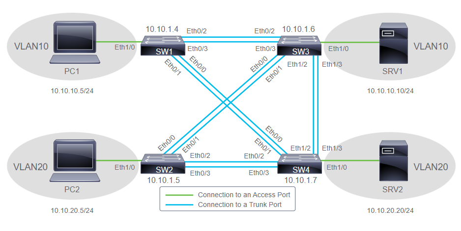
# int range e 0/1 - 2
# channel-group 2 mode active
# do sh etherchan sum
Group   Port-channel  Protocol  Ports
-------------------------------------
2       Po2(SU)       LACP      Et0/1(P)  Et0/2(P)

# do sh ip int br
Interface       IP-Address  OK?   Method  Status  Protocol
Port-channel2   unassigned  YES   unset   yes     up
-
Configuring Etherchannel on Layer2
>>> 'The configuration that follows applies to all 4 interfaces' >>> 'shutdown: Disabling interfaces ensure that incomplete configuration will not start to create activity on the link' >>> 'channel-group: port-channel number 1 as identifier and actives mode for enables LACP' SW1(config)# int range Gi0/1-4 SW1(config-if-range)# shutdown SW1(config-if-range)# channel-group 1 mode active SW1(config-if-range)# exit >>> 'configuring the port-channel interface ensure consistent configuration of all member interface' SW1(config)# int port-channel 1 SW1(config-if)# switchport mode trunk SW1(config-if)# switchport trunk allowed vlan 1,2,20 SW1(config-if)# int range Gi0/1-4 SW1(config-if-range)# no shut >>> 'The configuration repeats on SW2 for interfaces Gi1/1-4' - Configuring Etherchannel on Layer3
>>> 'a logical port-channel interface identified by the number 3 is created' >>> 'no switchport command turns interface into routed interface' >>> 'IP address is assigned to the routed port-channel 3 interface' SW1(config)# int port-channel 3 SW1(config-if)# no switchport SW1(config-if)# ip address 172.16.3.10 255.255.255.0 >>> 'the configuration that follows applies to all 4 interfaces' >>> 'no switchport command turns all member interfaces into a routed interface' >>> 'static etherchannel manually established and is used on platforms that do not support LACP' SW1(config-if)# int range Gi0/1-4 SW1(config-if-range)# no switchport SW1(config-if-range)# channel-group mode on SW1(config-if-range)# exit -
Verify Etherchannel Configuration
  SW1# sh int port-channel1
  Port-channel1 is up, line protocol is up (connected)

  SW1# sh etherchannel sum
  Group   Port-channel  Protocol  Ports
  -------------------------------------
  1       Po1(SU)       LACP      Et0/1(P)  Et0/2(P)

  SW1# sh etherchannel Port-channel
  Group: 1
  Port-channel: Po1    (Primary Aggregator)
  Protocol  =   LACP
  Index   Load   Port     EC state        No of bits
  ------+------+------+------------------+-----------
    0     00     Fa0/1    Active             4
    1     00     Fa0/2    Active             4

  SW1# sh ip route
  O 172.16.2.0 [110/2] via 192.168.1.2, 00:02:37, Port-channel5
  C 192.168.1.0/24 is directly connected, Port-channel5
Configuring and Verify Etherchannel
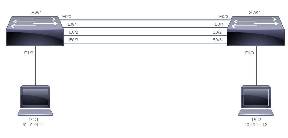
SW1# sh int status
Port      Name               Status       Vlan       Duplex  Speed Type
Et0/0     Link to SW4        connected    trunk        auto   auto unknown
Et0/1     Link to SW4        connected    trunk        auto   auto unknown
Et0/2     Link to SW3        connected    trunk        auto   auto unknown
Et0/3     Link to SW3        connected    trunk        auto   auto unknown
Et1/0     Link to PC1        connected    10           auto   auto unknown

SW1# sh spann vlan 10
Interface           Role Sts Cost      Prio.Nbr Type
------------------- ---- --- --------- -------- --------------------------------
Et0/0               Altn BLK 100       128.1    Shr
Et0/1               Altn BLK 100       128.2    Shr
Et0/2               Root FWD 100       128.3    Shr
Et0/3               Altn BLK 100       128.4    Shr
Et1/0               Desg FWD 100       128.5    Shr

SW3# sh spann vlan 10
Interface           Role Sts Cost      Prio.Nbr Type
------------------- ---- --- --------- -------- --------------------------------
Et0/0               Desg FWD 100       128.1    Shr
Et0/1               Desg FWD 100       128.2    Shr
Et0/2               Desg FWD 100       128.3    Shr
Et0/3               Desg FWD 100       128.4    Shr
Et1/0               Desg FWD 100       128.5    Shr
Et1/2               Desg FWD 100       128.7    Shr
Et1/3               Desg FWD 100       128.8    Shr

SW1# conf t
SW1(config)# int ran e0/2-3
SW1(config-if-range)# shut

SW3# conf t
SW3(config)# int ran e0/2-3
SW3(config-if-range)# shut

SW1(config-if-range)# channel-group 1 mode active
SW1(config-if-range)# no shut
SW1(config-if-range)# description Echannel to SW3

SW3(config-if-range)# channel-group 1 mode active
SW3(config-if-range)# no shut
SW1(config-if-range)# description Echannel to SW1

SW1(config-if-range)# do sh int status
Port      Name               Status       Vlan       Duplex  Speed Type
Et0/2     Echannel to SW1    connected    trunk        auto   auto unknown
Et0/3     Echannel to SW1    connected    trunk        auto   auto unknown

SW1# sh spann vlan 10
Interface           Role Sts Cost      Prio.Nbr Type
------------------- ---- --- --------- -------- ------------------
Po1                 Desg FWD 56        128.65   Shr

SW1# sh int po 1
Port-channel1 is up, line protocol is up (connected)

SW1# sh etherchannel port-channel
Group: 1
Port-channel: Po1    (Primary Aggregator)
Protocol  =   LACP
Index   Load   Port     EC state        No of bits
------+------+------+------------------+-----------
  0     00     Et0/2    Active             0
  0     00     Et0/3    Active             0

SW1# sh etherchannel sum
Group  Port-channel  Protocol    Ports
------+-------------+-----------+------------------
1      Po1(SU)         LACP      Et0/2(P)    Et0/3(P)
SW1> en
SW1# conf t
SW1(config)# int ran e0/0-3
SW1(config-if-range)# shut
SW1(config-if-range)# channel-group 12 mode active

SW2> en
SW2# conf t
SW2(config)# int ran e0/0-3
SW2(config-if-range)# shut
SW2(config-if-range)# channel-group 12 mode passive

SW1(config)# int port-channel 12
SW1(config-if)# switchport trunk encapsulation dot1q
SW1(config-if)# switchport mode trunk
SW1(config-if-range)# exit

SW2(config)# int port-channel 12
SW2(config-if)# switchport trunk encapsulation dot1q
SW2(config-if)# switchport mode trunk
SW2(config-if-range)# exit

SW1(config)# int ran e0/0-3
SW1(config-if-range)# no shut

SW2(config)# int ran e0/0-3
SW2(config-if-range)# no shut

PC1> en
PC1# ping 10.10.11.12

PC2> en
PC2# ping 10.10.11.11

SW1# sh int trunk
Port        Mode             Encapsulation  Status        Native vlan
Po12        on               802.1q         trunking      1

SW2# sh etherchannel sum
Group  Port-channel  Protocol    Ports
------+-------------+-----------+-----------------------------------------------
12     Po12(SU)        LACP      Et0/0(P)    Et0/1(P)    Et0/2(P)
                                 Et0/3(P)
20. Exploring Layer 3 Redudancy
Cisco Routers/Switchs support 3 FHRP protocol:
- HSRP (Hot Standby Router Protocol): is an FHRP that Cisco design to create redundancy framework between network router/L3 switches to achieve gateway failover capabilities.
- Virtual Router Redundancy Protocol (VRRP): is an open FHRP standard that offers the ability to add more than two routers for additional redundancy.
- Gateway Load Balancing Protocol (GLBP): is an FHRP that Cisco designed to allow multiple active forwarders to load-balance outgoing traffic on a per host basis rather than a per subnet basis like HSRP.
FHRP steps-by-steps:
- The standby router (secondary router) stops seeing hello message from the forwarding router (primary router)
- The standby router assumes the role of the forwarding router
- Because the new forwarding router assumes both the IP and MAC addresses of the virtual router, the end stations see no disruption in service.
Understanding HSRP
- Active Router HSRP:
- Responds to default gateway ARP Request with the virtual router MAC Address
- Assumes active forwarding of packets for the virtual router
- Sends hello messages between the active and standby routers
- Knows the virtual router IPv4 address
- Standby Router:
- Sends hello messages
- Listens for periodic hello messages
- Assumes active forwarding of packets if it does not hear from active router
- Sends Gratuitous ARP message when standby becomes active.
- The
standby preemptcommand enables the HSRP router with the highest priority to immediately become the active router. - HSRP Advanced features: to increase network availability and performance
- Load Balancing: Routers can simultaneously provide redundant backup and perform load sharing across various subnets and VLANs.
- Interface Tracking: When a tracked interface becomes unavailable, the HSRP tracking feature ensures that a router with the unavailable interface will relinquish the active router role.
21. Introducing WAN Technologies
Introducing WAN Technologies:
- WAN have three major characteristics:
- WANs generally connect devices that are separated by a broader geographic area than a LAN can serve.
- WANs use the services of carriers such as telephone companies, cable companies, satellite systems, and network providers.
- WANs use connections of various types of provide access to bandwidth over large geographic area.
- Business require communication with distant site because:
- people and process are in the regional and branch offices.
- Enterprise often share information with other organizations across large distance
- Employee who work from remote need access to their corporate network
- Applicatios and services used by employees can be hosted in the cloud.
WAN Devices:
- Modems are modulate and demodulate analog carriers to encode and retrieve digital information. Modem DSL (Digital Subscriber Line).
- Optical Fiber Converters are used where a fiber-optic link terminates to convert optical signals into electrical signals and vice versa. It can be use as router or switch.
- Router provides internetworking and WAN access interface ports that are used to connect to service provider network.
- Core Router resides within the middle or backbone of the WAN.
- Wireless Routers or access point are used when you are using the wireless medium for WAN connectivity.
- DTE/DCE and CSU/DSU (Data terminating/communicating equipment) translate data from LAN to WAN and WAN to LAN “language”. DTE > DCE > Service Provider > DCE > DTE. when use a digital line (Telp or coax), it use CSU/DSU. When connecting a digital device to an analog circuit, the DCE is a modem.
WAN Topology Options
- Point-to-point topology establishes a circuit between exactly two sites, typically offered in the form of leased lines.
- Hub-and-spoke topology a central router or multilayer switch, acting as the hub, which is connected to all other remote devices, the spokes.
-
Meshed Topologies
- Full Mesh each remote node have direct connections to all other nodes
- Partial Mesh almost, but not all other remote nodes are interconnected.
- Single Carrier WAN only have 1 connection carriers to ISP
- Dual Carrier WAN means the enterprise has connection to two different carriers to 2 different ISP.
WAN Connectivity Options:
- A WAN consist of:
- Local-loop/last-mile network represents end user connections to the service provider. Example line from home to ISP.
- Backhaul network which connect multiple access nodes of the service provider’s network.
- The backbone network is interconnects service provider’s networks.
- emergin WAN connectivity options can be broadly classified into:
- Dedicated Communication links provide permanent dedicated connections using point-to-point links with various capacities that are limited only to enterprise dedicated line.
- Switched communication links is circuit switch or packet-switch that establishes a dedicated or shared connection with dynamically data flow fluctuations.
- Internet-based Communication Links use global internet infrastructure for WAN connectivity, using VPN technology for cheap and secure.
- Traditional Connectivity
- Lease lines are example of legacy dedicated communication links.
- Two types of
circuit-switchedWAN:- PSTN Analog transported through the voice telephone network using a device called modem.
- ISDN connections enables the local loop of a PSTN to carry digital signals in higher capacity.
- Two types of
packet-switchedWAN:- Frame Relay is layer2 technology which defines virtual circuit (VC), represent end-to-end link mapped over the Frame Relay WAN.
- ATM is built on a cell-based architecture rather than on a frame-based architecture. It don’t have to wait for larger data packets to be transmitted.
- Current and Emerging WAN Connectivity
- Multiprotocol Label Switching (MPLS) is an IETF standard that define a packet label-based switching technique, which was originally devised to perform fast switching in the core of IP networks.
- Ethernet over WAN or metro ethernet can be deployed in several ways such as pure ethernet connectivity, ethernet over SDH/SONET, MPLS based deployment. This deployment reduce expenses and administration, Easy integration with existing networks, enhanced business productivity.
-
Broadband Internet Access
- Wired Broadband Internet Access need 2 types of equipment: Cable Modem, Cable Modem Termination System
- Wireless Broadband Internet Access: Municipal Wi-Fi, Cellular/Mobile, Satelite Internet, WiMAX
- Optical Fiber in WAN Connection
- Fiber to the X is optical fiber network architectures, in which reaches the subscriber home, premises, or building.
- SONET and SDH is WAN physical layer to transfer multiple data, voice, and video communications over optical fiber using lasers or light-emitting diodes (LED) over great distances.
-
Dense Wavelength-Division Multiplexing
- Assigns incoming optical signals to specific wavelength of light (frequency)
- Can multiplex morethan 96 different channels of data onto a single fiber
- Each channel is capable of carrying a 200Gbps multiplexed signal
- Can amplify these wavelengths to boost the signal strength
- is protocol agnostic
- Dark Fiber used for interconnect their remote locations directly.
- WAN-Related Protocols (PPP) is an encapsulation protocol for transpoting IP traffic over point-to-point links, such as links in analog dialup and ISDN access networks.
- Enterprise Internet Connectivity Options
- Single-homed use only one service provider for the internet uplink and no redundancy.
- Dual-homed two link toward the same ISP and configured to load balance traffic, no redundancy if the ISP has an outage.
- Multihomed connected to multiple ISP, it provides more than redundancy and enables load-balancing
- Dual-multihomed enhance resiliency and most redundancy possible with two links to each ISP but most costly options.
VPN (Virtual Private Networks)
- VPN are classified into:
- Deployment Mode: Site-to-site VPN (connect 2 sites) and remote access VPN (connect remote VPN client).
- Underlying Technology: IPsec VPN, SSL VPN, MPLS VPN, hybrid VPN combining multiple technology.
- VPN benefits:
- Cost Savings
- Scalability
- Compatibility with broadband technology
- Security
Enterprise-Managed VPNs
- Deployment modes in enterprise-managed VPNs:
- Site-to-site VPNs
- Remote-access VPNs
- Site-to-site VPN options:
- IPsec tunnel is a framework of open standards that spells out the rules for secure communications. It provides a secure method for tunneling data across an IP network, it has limitations.
- Generic Routing Encapsulation (GRE) over IPsec is a tunneling protocol developed by Cisco that can encapsulate a wide variety of network layer protocol packet types and non-ip protocols.
- Cisco Dynamic Multipoint Virtual Private Network (DMVPN) is Cisco proprietary software solution that simplifies the device configuration when there is a neeed for many VPN connection.
- IPsec Virtual Tunnel Interface (VTI) is a feature that associates an IPsec tunnel endpoint with virtual interface.
- Provider-managed VPN:
- Layer2 MPLS VPNs ISP is useful for customer who run their own Layer3 infrastructure and require only Layer2 connectivity from the ISP.
- Layer3 MPLS VPNs ISP provides a Layer3 service across the backbones.
22. Explaining the Basics of ACL
ACL features for packet filtering
- Limit network traffic to increase network performance
- Provide traffic flow control
- Provide a basic level of security for network access
- Filter traffic based on traffic type
- Screen hosts to permit or deny access to network services
ACL Wildcard Masking
| Wildcard | Ref IPv4 | Match Pattern | Match Octet |
|---|---|---|---|
| 00000000 | 01100100 | 01100100 | 100 |
| 00000001 | 01100100 | 0110010x | 100, 101 |
| 00000011 | 01100100 | 011001xx | 100, 101, 102, 103 |
| 00000111 | 01100100 | 01100xxx | 96-103 |
| 00001111 | 01100100 | 0110xxxx | 96-111 |
| 00011111 | 01100100 | 011xxxxx | 96-127 |
| 00111111 | 01100100 | 01xxxxxx | 64-127 |
| 01111111 | 01100100 | 0xxxxxxx | 0-127 |
| 11111111 | 01100100 | xxxxxxxx | 0-255 |
| Matching Rule | Wildcard Mask | Resulting Pattern | Match Pattern |
|---|---|---|---|
| 172.16.100.0 | 0.0.0.255 | 172.16.100.x | 01100100 |
| 172.16.100.1 | 0.0.0.255 | 172.16.100.x | 01100100 |
| 192.168.5.1 | 0.0.254.255 | 192.168.odd#.x | xxxxxxx1 |
| 172.16.16.0 | 0.0.0.255 | 172.16.16.x | 00010000 |
| 172.16.16.1 | 0.0.15.255 | 172.16.16.x - 172.16.31.x | 0001xxxx |
| Rule with wildcard | rule with keywords |
|---|---|
| 172.30.16.5 0.0.0.0 | host 172.30.16.5 |
| 172.30.16.5 0.0.0.0 | 172.30.16.5 |
| 172.30.16.5 255.255.255.255 | any |
Type of Basic ACLs
- Two basic types of ACLs:
- Standard IP ACLs: specify matching rules for source addresses of packets only, without concerning the destination addresses.
- Extended IP ACLs: examine both the source and destination IP addresses, more flexibility and controll especially for check protocols, port number, and other parameters.
- Two general methods to create ACLs:
- Numbered ACLs use a number for identification of the specific access list. It;s effective method on smaller networks with more homogeneously defined traffic.
- Named ACLs allow you to identify ACXL with descriptive alphanumeric name instead of the numeric representation.
Configuring Standard IPv4 ACLs
  R1(config)# access-list access-list-number permit|deny source [source-wildcard] | host {address|name} | any

  R1(config)# ip access-list standard access-list-name
  R1(config-std-nacl)# [sequence-number] permit|deny source [source-wildcard] | host {address|name} | any

  EXAMPLE Numbered standard ACL Configuration Method:
  R1(config)# access-list 1 deny host 172.16.3.3
  R1(config)# access-list 1 permit 172.16.0.0 0.0.255.255

  EXAMPLE Named standard ACL Configuration Method:
  R1(config)# ip access-list standard acl2
  R1(config-std-nacl)# deny host 172.16.3.3
  R1(config-std-nacl)# permit 172.16.0.0 0.0.255.255
Configuring Extended IPv4 ACLs
  R1(config)# access-list access-list-number permit|deny protocol source_matching_criteria destination_matching_criteria

  R1(config)# ip access-list extended access-list-name
  R1(config-ext-nacl)# [sequence-number] permit | deny protocol source_matching_criteria destination_matching_criteria

  EXAMPLE numbered extended ACL
  R1(config)# access-list 101 deny tcp 172.16.3.0 0.0.0.255 any eq 22
  R1(config)# access-list 101 deny tcp 172.16.3.0 0.0.0.255 any eq telnet
  R1(config)# access-list 101 permit ip 172.16.3.0 0.0.0.255 any

  EXAMPLE named extended ACL
  R1(config)# ip access-list extended 101
  R1(config-ext-nacl)# deny tcp 172.16.3.0 0.0.0.255 any eq 22
  R1(config-ext-nacl)# deny tcp 172.16.3.0 0.0.0.255 any eq 23
  R1(config-ext-nacl)# permit ip 172.16.3.0 0.0.0.255 any
Verifying and Modifying IPv4 ACLs
  R1# show access-lists 1
  Standard IP access list 1
    10 deny host 172.16.3.3
    20 permit 172.16.0.0 0.0.255.255

  R1# show access-lists 101
  Extended IP access list 101
    10 deny tcp 172.16.3.0 0.0.0.255 any eq 22
    20 deny tcp 172.16.3.0 0.0.0.255 any eq telnet
    30 permit ip 172.16.3.0 0.0.0.255 any

  R1(config)# ip access-list standard 1
  R1(config-std-nacl)# 15 deny host 172.16.4.4
  R1# show access-lists 1
  Standard IP access list 1
    10 deny host 172.16.3.3
    15 deny host 172.16.4.4
    20 permit 172.16.0.0 0.0.255.255

  R1(config)# ip access-list standard 1
  R1(config-std-nacl)# no 15
Applying IPv4 ACLs to Filter Network Traffic
- When you use Standard ACL is placed close to the destination of traffic as possible, because it will not consume network resources and blocking guest to access the internet.
- When you use Extended ACL is placed close to the source of discarded traffic as possible, it placed on the router closest to the Guest VLAN and prevent it from crossing other device.
- ACL Parameters:
- the extent of the network administrator control:
- Bandwidth of the networks involved:
- Ease of Configuration:
- How packet processing occurs on ACLs:
- Inbound ACL process incoming packets and inbound ACL is efficient bcs it saves the overhead routing lookups if the packet is discarded.
- Outbound ACL process packets that are routed to the outbound interface before they exit the interface ```bash R1(config-if)# ip access-group {access-list-number | access-list-name} {in | out}
EXAMPLE Extended ACL inbound and outbound R1(config-if)# ip access-group 101 in R1(config-if)# ip access-group PERMIT_ICMP out
EXAMPLE Remove ACL from interface R1(config-if)# no ip access-group –> Remove ACL from interface R1(config-if)# no access-list –> Remove entire ACL ```
- You can configure one ACL per protocol, per direction, per interface:
- One ACL per protocol: you have to create and apply two access list for each protocol IPv4 and IPv6.
- One ACL per direction: two seperate ACLs may be created to control both inbound and outbound traffic on an interface, or use same ACL to apply it in both directions. ```bash EXAMPLE deny internet access for PC2 R1# sh access-lists Standard IP access list 15 10 deny 10.1.1.101 20 permit 10.1.1.0 0.0.0.255 R1(config)# int Gi0/1 R1(config-if)# ip access-group 15 out
R1# sh access-lists Extended IP access list NOINTERNET_PC2 10 deny ip host 10.1.1.101 any 20 permit ip 10.1.1.0 0.0.0.255 any R1(config)# int Gi0/0 R1(config-if)# ip access-group NONINTERNET_PC2 in ```
Configure and Verify IPv4 ACLs
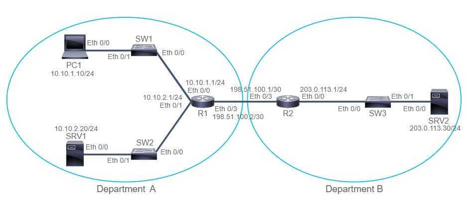
  R1# sh run | i access-list
  access-list 10 permit 10.10.1.10
  access-list 10 deny 10.10.1.0 0.0.0.255
  access-list 10 permit 10.10.0.0 0.0.255.255
  access-list 10 deny 10.0.0.0 0.255.255.255
  access-list 10 permit any

  R1# conf t
  R1(config)# int e0/3
  R1(config-if)# ip access-group 10 out

  PC1# ping 203.0.113.30 --> success (IP 10.10.1.10)

  R1# sh access-list 10
  Standard IP access-list 10
    10 permit 10.10.1.10 (5 matchses)
    20 deny 10.10.1.0 wildcard bits 0.0.0.255
    30 permit 10.10.0.0 wildcard bits 0.0.255.255
    40 deny 10.0.0.0 wildcard bits 0.255.255.255
    50 permit any

  SW1# ping 203.0.113.30 --> failed (IP 10.10.1.0)

  R1# sh access-list 10
  Standard IP access-list 10
    10 permit 10.10.1.10 (5 matchses)
    20 deny 10.10.1.0 wildcard bits 0.0.0.255 (8 matches)
    30 permit 10.10.0.0 wildcard bits 0.0.255.255
    40 deny 10.0.0.0 wildcard bits 0.255.255.255
    50 permit any

  R2# ping 10.10.2.20 --> success (IP 10.10.2.20)

  R1# sh access-list 10
  Standard IP access-list 10
    10 permit 10.10.1.10 (5 matchses)
    20 deny 10.10.1.0 wildcard bits 0.0.0.255 (8 matches)
    30 permit 10.10.0.0 wildcard bits 0.0.255.255 (4 matches)
    40 deny 10.0.0.0 wildcard bits 0.255.255.255
    50 permit any

  R1# ping 203.0.113.30 source 198.51.100.2 --> success (198.51.100.2)
  R1# sh access-list 10
  Standard IP access-list 10
    10 permit 10.10.1.10 (5 matchses)
    20 deny 10.10.1.0 wildcard bits 0.0.0.255 (8 matches)
    30 permit 10.10.0.0 wildcard bits 0.0.255.255 (4 matches)
    40 deny 10.0.0.0 wildcard bits 0.255.255.255
    50 permit any

  R1# conf t
  R1(config)# access-list 10 deny 10.10.2.0 0.0.0.255
  R1(config)# do sh access-list
  Standard IP access-list 10
    10 permit 10.10.1.10 (5 matchses)
    20 deny 10.10.1.0 wildcard bits 0.0.0.255 (8 matches)
    30 permit 10.10.0.0 wildcard bits 0.0.255.255 (4 matches)
    40 deny 10.0.0.0 wildcard bits 0.255.255.255
    50 permit any
    60 deny 10.10.2.0 wildcard bits 0.0.0.255

  R1(config)# access-list 10 permit host 10.10.2.20 --> can't accept the rule
  R1(config)# do sh access-list
  Standard IP access-list 10
    10 permit 10.10.1.10 (5 matchses)
    20 deny 10.10.1.0 wildcard bits 0.0.0.255 (8 matches)
    30 permit 10.10.0.0 wildcard bits 0.0.255.255 (4 matches)
    40 deny 10.0.0.0 wildcard bits 0.255.255.255
    50 permit any
    60 deny 10.10.2.0 wildcard bits 0.0.0.255

  R1(config)# ip access-list stand 10
  R1(config-std-nacl)# no 60
  R1(config-std-nacl)# 24 permit host 10.10.2.20
  R1(config-std-nacl)# 27 deny 10.10.2.0 0.0.0.255
  R1(config-std-nacl)# do sh ip access-list 10
    10 permit 10.10.1.10 (5 matchses)
    24 permit 10.10.2.20
    20 deny 10.10.1.0 wildcard bits 0.0.0.255 (8 matches)
    27 deny 10.10.2.0 wildcard bits 0.0.0.255
    30 permit 10.10.0.0 wildcard bits 0.0.255.255 (4 matches)
    40 deny 10.0.0.0 wildcard bits 0.255.255.255
    50 permit any

  SRV1# ping 203.0.113.30 --> Success (10.10.2.20)
  R1(config-std-nacl)# do sh ip access-list 10
    10 permit 10.10.1.10 (5 matchses)
    24 permit 10.10.2.20 (5 matchses)
    20 deny 10.10.1.0 wildcard bits 0.0.0.255 (8 matches)
    27 deny 10.10.2.0 wildcard bits 0.0.0.255
    30 permit 10.10.0.0 wildcard bits 0.0.255.255 (4 matches)
    40 deny 10.0.0.0 wildcard bits 0.255.255.255
    50 permit any

  SW2# ping 203.0.113.30 --> failed (10.10.2.1)
  R1(config-std-nacl)# do sh ip access-list 10
    10 permit 10.10.1.10 (5 matchses)
    24 permit 10.10.2.20 (5 matchses)
    20 deny 10.10.1.0 wildcard bits 0.0.0.255 (8 matches)
    27 deny 10.10.2.0 wildcard bits 0.0.0.255 (8 matches)
    30 permit 10.10.0.0 wildcard bits 0.0.255.255 (4 matches)
    40 deny 10.0.0.0 wildcard bits 0.255.255.255
    50 permit any
  R1# conf t
  R1(config)# ip access-list stand 10
  R1(config-std-nacl)# no 10
  R1(config-std-nacl)# no 20
  R1(config-std-nacl)# do sh ip access-list 10
  Standard IP access list 10
    24 permit 10.10.2.20
    27 deny 10.10.2.0 wildcard bits 0.0.0.255
    30 permit 10.10.0.0 wildcard bits 0.0.255.255
    40 deny 10.0.0.0 wildcard bits 0.255.255.255
    50 permit any

  SW1# ping 203.0.113.30 --> success (10.10.1.0)
  SW2# ping 203.0.113.30 --> failed (10.10.2.1) bcs standard ACL still have in place

  R1(config)# ip access-list extended PC1_TELNET
  R1(config-ext-nacl)# deny udp any any
  R1(config-ext-nacl)# permit tcp host 10.10.1.10 any eq 23
  R1(config-ext-nacl)# deny tcp host 10.10.1.10 any
  R1(config-ext-nacl)# permit ip any any
  R1(config-ext-nacl)# int e0/0
  R1(config-if)# ip access-group PC1_TELNET in
  R1(config-if)# do sh access-list
  Standard IP access list 10
    24 permit 10.10.2.20
    27 deny 10.10.2.0 wildcard bits 0.0.0.255
    30 permit 10.10.0.0 wildcard bits 0.0.255.255
    40 deny 10.0.0.0 wildcard bits 0.255.255.255
    50 permit any
  Extended IP access list PC1_TELNET
    10 deny udp any any
    20 permit tcp host 10.10.1.10 any eq telnet
    30 deny tcp host 10.10.1.10 any
    40 permit ip any any

  PC1# ping R2 --> can not talk to DNS server (block by ACL)
  PC1# ping 198.51.100.1 ---> success (10.10.1.10) to R2
  PC1# telnet 203.0.113.30 --> success (10.10.1.10) to SVR2
  PC1# telnet 203.0.113.30 80 --> failed (10.10.1.10) to SVR2 bcs only allow port 23

  R1(config-if)# do sh access-list
  Standard IP access list 10
    24 permit 10.10.2.20
    27 deny 10.10.2.0 wildcard bits 0.0.0.255
    30 permit 10.10.0.0 wildcard bits 0.0.255.255
    40 deny 10.0.0.0 wildcard bits 0.255.255.255
    50 permit any
  Extended IP access list PC1_TELNET
    10 deny udp any any (1 matches)
    20 permit tcp host 10.10.1.10 any eq telnet (39 matches)
    30 deny tcp host 10.10.1.10 any (1 matches)
    40 permit ip any any (5 matches)

  PC1# ping 10.10.2.20 --> success (10.10.1.10) to SRV1
  SRV1# ping 203.0.113.30 --> success (10.10.2.20) to SRV2
  SRV1# ping 198.51.100.1 --> success (10.10.2.20) to R2
  SRV1# telnet 203.0.113.30 --> success (10.10.2.20) to SRV2
  SRV1# telnet 203.0.113.30 80 --> success (10.10.2.20) to SRV2
  R1(config-if)# do sh access-list PC1_TELNET --> no one hit ACL
  Extended IP access list PC1_TELNET
    10 deny udp any any (1 matches)
    20 permit tcp host 10.10.1.10 any eq telnet (39 matches)
    30 deny tcp host 10.10.1.10 any (1 matches)
    40 permit ip any any (5 matches)
Implement Numbered and Named IPv4 ACLs
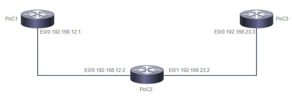
  PoC2> en
  PoC2# conf t
  PoC2(config)# access-list 1 deny 172.16.1.1
  PoC2(config)# access-list 1 permit 172.16.1.0 0.0.0.255
  PoC2(config)# access-list 1 deny 172.16.2.0 0.0.0.255
  PoC2(config)# access-list 1 permit any

  PoC2(config)# int E0/0
  Poc2(config-if)# ip access-group 1 out
  Poc2(config-if)# exit

  PoC2(Config)# ip access-list standard NAMED_ACL
  PoC2(Config-std-nacl)# permit host 192.168.12.1
  PoC2(Config-std-nacl)# permit 10.1.1.0 0.0.0.3
  PoC2(Config-std-nacl)# permit 10.1.2.0 0.0.1.255
  PoC2(Config-std-nacl)# exit
  PoC2(config)# int E0/0
  Poc2(config-if)# ip access-group NAMED_ACL in
  Poc2(config-if)# exit

  PoC2(config)# ip access-list extended PING_31
  PoC2(config-ext-nacl)# permit icmp host 192.168.23.3 any
  PoC2(config-ext-nacl)# deny icmp any any
  PoC2(config-ext-nacl)# permit ip any any
  PoC2(config-ext-nacl)# exit

  PoC2(config)# int E0/1
  Poc2(config-if)# ip access-group PING_31 in
23. Enabling Internet Connectivity
Enterprise Internet Connectivity Options
- the advantages of dynamic address assignment is:
- Reduced configuration time
- Reduced probability of configuration errors
R1(config)# int E0/0
R1(config-if)# ip address dhcp
- Optaining IPv4 address information from DHCP server:
- The router requests IPv4 address information from the DHCP server
- The router injects a statics default route in its routing table based on the default gateway parameters received with the assigned IPv4 address
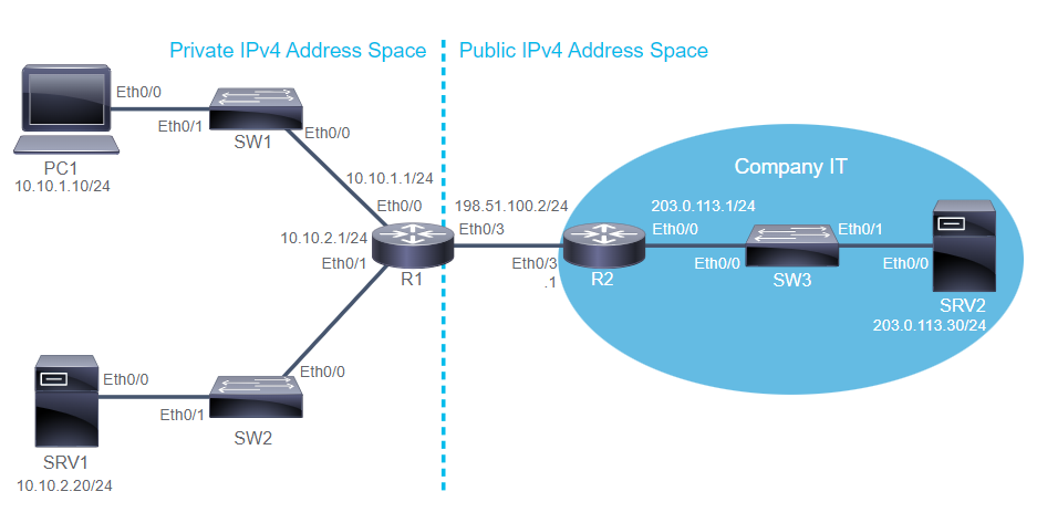
  R1# sh ip int br
  Interface                  IP-Address      OK? Method Status                Protocol
  Ethernet0/3                198.51.100.2    YES NVRAM  up                    up

  R1# sh ip ro
  Gateway of last resort is not set
        10.0.0.0/8 is variably subnetted, 4 subnets, 2 masks
  C        198.51.100.0/24 is directly connected, Ethernet0/3
  L        198.51.100.2/32 is directly connected, Ethernet0/3

  R1# conf t
  R1(config)# int E0/3
  R1(config-if)# ip address dhcp
  R1(config-if)# end
  R1#
  *Apr 19 14:47:21.312: %DHCP-6-ADDRESS_ASSIGN: Interface Ethernet0/3 assigned DHCP address 198.51.100.101, mask 255.255.255.0, hostname R1

  R1# sh ip int br
  Interface                  IP-Address      OK? Method Status                Protocol
  Ethernet0/3                198.51.100.101  YES DHCP   up                    up

  R1# sh ip ro
  Gateway of last resort is 198.51.100.1 to network 0.0.0.0
  S*    0.0.0.0/0 [254/0] via 198.51.100.1
        10.0.0.0/8 is variably subnetted, 4 subnets, 2 masks
  C        198.51.100.0/24 is directly connected, Ethernet0/3
  L        198.51.100.101/32 is directly connected, Ethernet0/3

  R1# ping 203.0.113.30 --> success (198.51.100.101) to srv2

  PC1# conf t
  PC1(config)# no ip default-gateway 10.10.1.1
  PC1(config)# int E0/0
  PC1(config-if)# ip address dhcp
  PC1(config-if)# end
  PC1# sh ip int br
  Interface                  IP-Address      OK? Method Status                Protocol
  Ethernet0/0                unassigned      YES DHCP   up                    up

  PC1# sh ip ro
  Default gateway is not set
  Host               Gateway           Last Use    Total Uses  Interface
  ICMP redirect cache is empty

  R1# conf t
  R1(config)# int E0/0
  R1(config-if)# ip helper-address 198.51.100.1
  R1(config-if)# end

  PC1#
  *Apr 19 11:19:11.381: %DHCP-6-ADDRESS_ASSIGN: Interface Ethernet0/0 assigned DHCP address 10.10.1.101, mask 255.255.255.0, hostname PC1
  PC1# sh ip int br
  Interface                  IP-Address      OK? Method Status                Protocol
  Ethernet0/0                10.10.1.101     YES DHCP   up                    up

  PC1# sh ip ro
  Default gateway is 10.10.1.1
  Host               Gateway           Last Use    Total Uses  Interface
  ICMP redirect cache is empty

  PC1# sh dhcp lease
  Temp IP addr: 10.10.1.101  for peer on Interface: Ethernet0/0
  Temp  sub net mask: 255.255.255.0
    DHCP Lease server: 198.51.100.1, state: 5 Bound
  Temp default-gateway addr: 10.10.1.1
    Hostname: PC1

  PC1# sh dhcp server
    DHCP server: ANY (255.255.255.255)
      Subnet: 255.255.255.0

  R2# show startup-config | section dhcp
  ip dhcp excluded-address 198.51.100.1 198.51.100.100
  ip dhcp excluded-address 10.10.1.1 10.10.1.100
  ip dhcp pool ClientRouter
  network 198.51.100.0 255.255.255.0
  default-router 198.51.100.1
  lease 7
  ip dhcp pool Client_10_10_1_0
  network 10.10.1.0 255.255.255.0
  default-router 10.10.1.1
  lease 5
Introducing IPv4 Address Translation (NAT)
- NAT is a protocol that is used for connecting or translating multiple devices on internet, private networks to a public network such as the internet, using a limited number of Public IPv4 addresses.
- NAT is usually implemented on border devices such as firewalls or servers.
- NAT can also be used for generic translations between any two different IPv4 address spaces.
NAT Terminology and Translation Mechanism
- NAT terminology categorized into 2 types:
- classification divided addresses based on the exist in the network:
- Inside Addresses are that belong to the network and addresses of devices internal to the network.
- Outside Addresses all addresses that don’t belong to the network and refers to all other addresses.
- classification devides addresses based on where they are “viewed”:
- Local Addresses: are devices values that are “seen” by a local devices or values that intended to be used by the devices in the local(inside) network.
- Global Addresses: are address values as seen globally or values meant be used by the devices external network.
- classification divided addresses based on the exist in the network:
- All combination of two types addresses:
- Inside local addresses: IP address of an inside network device that is used in all packets that remain in the inside network. (192.168.10.10)
- Inside global addresses: Ip address of an internal device as it appears to the external networks and translated inside local addresses. (209.165.200.226)
- Outside local addresses: IP addresses of an external devices as it appears to the internal network. (209.165.201.1)
- Outside global addresses: IP address of the an external device as seen externally. (209.165.201.1)
- NAT implementations:
- Static NAT maps a local IPv4 address to a global IPv4 address (one to one), it useful when when a device must be accessible from an external network. It’s never change.
- Dynamic NAT maps a local IPv4 address to pool of global IPv4 addresses. it working when an inside device accesses an outside network.
- NAPT or PAT is Network address and Port Translation or Port Address Translation. It maps multiple local IPv4 addresses to just a single global IPv4 addresses (many to one). PAT enables multiple local devices to access the internet, even when the device bordering th ISP has only public IPv4 address assigned. When inside network initiate communication to outside, the dynamic mapping will created with specific timeout. But NAT doesn’t allow reuests initiated from the outside.
No Inside LAN Outside/Internet 1 192.168.1.1:2222 209.165.200.226:2222 2 192.168.1.5:4444 209.165.200.226:4444
Benefit and Disadvantages of NAT
- Benefit of NAT:
- NAT conserves public addresses by enabling multiple privately addressed host to communicate using a limited, small number of public addresses.
- NAT increases the flexibility of connections to the public network
- NAT provides consistency for internal network addressing schemes.
- NAT can be configured to translate all private addresses to only one public address or to a smaller pool of public addresses.
- Disadvantages of NAT:
- End-to-end functionality is lost : NAT interferes by changing the IPv4 address and sometimes transport protocol port (PAT)
- End-to-end traceability is also lost: it become more difficult to trace or obtain the original source or destination addresses.
- create difficulties for the tunneling protocols such as IPsec, NAT changes intefere with the integrity checking mechanisms that IPsec and other tunneling protocol performs.
- Services that require the initiation of TCP connections from an outside network can be disrupted
- NAT can degrade network performance by increases forwarding delays because the translation of each IPv4 address within the packet headers.
Configuring and Verifying Inside IPv4 NAT
- To configure any of the NAT device:
- Specify inside and outside interfaces you must instruct the border device on where to expect the inside traffic that needs to be translated (inside interface) and where to inspect outside traffic (outside) that needs to be translated.
- Specify local addresses that need to be translated
- Specify Global Addresses available for translations
-
Specify NAT type using
ip nat inside sourcecommand
Specify inside and outside interfaces
  R1(config)# int Gi0/1
  R1(config-if)# ip addr 209.165.200.226 255.255.255.224
  R1(config-if)# ip nat outside --> public address
  R1(config-if)# exit
  R1(config)# int Gi0/0
  R1(config-if)# ip addr 172.16.1.1 255.255.255.0
  R1(config-if)# ip nat inside --> private address
  R1(config-if)# exit
Configuring Static Inside IPv4 NAT and Port Forwarding
  R1(config)# ip nat inside source static 172.16.1.10 209.165.200.230
  R1# sh ip nat translations
  Pro   Inside global         Inside local      Outside local       Outside global
  tcp   209.165.200.230:1031  172.16.1.10:1031  209.165.202.155:23  209.165.202.155:23
  ---   209.165.200.230       172.16.1.10       ---                 ---

  R2(config)# ip nat inside source static tcp 192.168.10.254 80 209.165.200.226 8080
  R2# sh ip nat translations
  Pro   Inside global         Inside local        Outside local   Outside global
  tcp   209.165.200.226:8080  192.168.10.254:80   ---             ---
Configuring Dynamic IPv4 Inside NAT
  R1(config)# access-list 1 permit 10.1.1.0 0.0.0.255
  R1(config)# ip nat pool NAT-POOL 209.165.200.230 209.165.200.235 netmask 255.255.255.224
  R1(config)# ip nat inside source list 1 pool NAT-POOL
  R1# sh ip nat translations
  Pro   Inside global     Inside local    Outside local   Outside global
  ---   209.165.200.230   10.1.1.100      ---             ---
  ---   209.165.200.231   10.1.1.101      ---             ---
Configuring IPv4 inside PAT
  R1(config)# access-list 1 permit 172.16.1.0 0.0.0.255
  R1(config)# ip nat inside source list 1 int Gi0/1 overload
  R1# sh ip nat translations
  Pro   Inside global      Inside local    Outside local       Outside global
  icmp  209.165.200.226:3  172.16.1.10:3   209.165.202.155:3   209.165.202.15:3
  icmp  209.165.200.226:1  172.16.1.9:1    209.165.201.25:1    209.165.201.25:1
  tcp   209.165.200.226:2  172.16.1.9:2    209.165.201.25:5    209.165.201.25:5
  tcp   209.165.200.226:4  172.16.1.9:2    209.165.201.25:5    209.165.201.25:5
Configure Static NAT
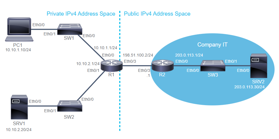
  R1# conf t
  R1(config)# int e0/3
  R1(config-if)# ip add 198.51.100.2 255.255.255.0
  R1(config-if)# exit
  R1(config)# ip route 0.0.0.0 0.0.0.0 198.51.100.1
  R1(config)# do sh ip route
  Gateway of last resort is 198.51.100.1 to network 0.0.0.0
  S*    0.0.0.0/0 [1/0] via 198.51.100.1
  C     198.51.100.0/24 is directly connected, Eth0/3
  L     198.51.100.2/31 is directly connected, Eth0/3

  R1(config)# do ping 203.0.113.30 --> success from 198.51.100.2 to SRV2

  SRV1# ping 203.0.113.30 --> failed from 10.10.2.20 to SRV2 (bcs no NAT in R1 and SRV2 can not get feedback to SRV1 which using private address)

  R1(config)# int e0/3
  R1(config-if)# ip nat outside
  R1(config-if)# int e0/1
  R1(config-if)# ip nat inside
  R1(config-if)# exit
  R1(config)# ip nat inside source static 10.10.2.20 198.51.100.20
  R1(config)# do sh ip nat translations
  Pro   Inside global      Inside local    Outside local       Outside global
  ---   198.51.100.20      10.10.2.20      ---                 ---

  SRV1# ping 203.0.113.30 --> success from 10.10.2.20 to SRV2

  R1(config)# do sh ip nat translations
  Pro   Inside global      Inside local    Outside local       Outside global
  icmp  198.51.100.20:1    10.10.2.20:1    203.0.113.30:1      203.0.113.30:1
  ---   198.51.100.20      10.10.2.20      ---                 ---

  SRV2# telnet 198.51.100.20 --> success from 203.0.113.30 to SRV1

  R1(config)# do sh ip nat translations
  Pro   Inside global      Inside local    Outside local       Outside global
  icmp  198.51.100.20:23   10.10.2.20:23   203.0.113.30:19295  203.0.113.30:19295
  ---   198.51.100.20      10.10.2.20      ---                 ---
Configure Dynamic NAT & PAT
  PC1# ping 203.0.113.30 --> failed from 10.10.1.10 to SRV2
  SW2# ping 203.0.113.30 --> failed from 10.10.2.1 to SRV2

  R1# sh ip nat statistics
  Total active translations: 1 (1 static, 0 dynamic, 0 extended)
  Outside interfaces: Ethernet 0/3
  Inside interfaces: Ethernet 0/1

  R1(config)# int e0/0
  R1(config-if)# ip nat inside
  R1(config-if)# exit
  R1(config)# access-list 10 permit 10.10.0.0 0.0.255.255
  R1(config)# ip nat pool NAT_POOL 198.51.100.100 198.51.100.149 netmask 255.255.255.0
  R1(config)# ip nat inside source list 10 pool NAT_POOL

  PC1# ping 203.0.113.30 --> success from 10.10.1.10 to SRV2
  SW2# ping 203.0.113.30 --> success from 10.10.2.1 to SRV2

  R1(config)# do sh ip nat trans
  Pro   Inside global      Inside local    Outside local       Outside global
  icmp  198.51.100.100:3   10.10.1.10:3    203.0.113.30:3      203.0.113.30:3
  ---   198.51.100.100     10.10.1.10      ---                 ---
  icmp  198.51.100.101:3   10.10.2.4:3     203.0.113.3:3       203.0.113.3:3
  icmp  198.51.100.101:4   10.10.2.4:4     203.0.113.30:4      203.0.113.30:4
  ---   198.51.100.101     10.10.2.4       ---                 ---
  ---   198.51.100.20      10.10.2.20      ---                 ---

  PC1# telnet 203.0.113.30 --> success from 10.10.1.10 to SRV2

  R1(config)# do sh ip nat trans
  Pro   Inside global      Inside local    Outside local       Outside global
  icmp  198.51.100.100:65  10.10.1.10:65   203.0.113.30:23     203.0.113.30:23
  ---   198.51.100.100     10.10.1.10      ---                 ---
  ---   198.51.100.101     10.10.2.4       ---                 ---
  ---   198.51.100.20      10.10.2.20      ---                 ---

  R1# sh ip nat statistics
  Total active translations: 4 (1 static, 3 dynamic, 1 extended)
  Outside interfaces: Ethernet 0/3
  Inside interfaces: Ethernet 0/1, Ethernet 0/0

  R1# clear ip nat translation *
  R1# sh ip nat trans
  Pro   Inside global      Inside local    Outside local       Outside global
  ---   198.51.100.20      10.10.2.20      ---                 ---
Configure Inside IPv4 PAT
  R1# conf t
  R1(config)# no ip nat pool NAT_POOL
  R1(config)# no ip nat inside source list 10 pool NAT_POOL

  PC1# ping 203.0.113.30 --> failed from 10.10.1.10 to SRV2 (because no NAT anymore)

  R1(config)# do sh ip nat trans
  Pro   Inside global      Inside local    Outside local       Outside global
  ---   198.51.100.20      10.10.2.20      ---                 ---

  R1(config)# ip nat inside source list 10 interface e0/3 overload

  PC1# telnet 203.0.113.30 --> success from 10.10.1.10 to SRV2
  SW1# telnet 203.0.113.30 --> success from 10.10.2.4 to SRV2
  SRV2> sh control-plane host open-ports
  Port    Local Address   Foreign Address       Service state
  tcp     *:23            198.51.100.2:15949    Telnet Establish
  tcp     *:23            198.51.100.2:19036    Telnet Establish
  tcp     *:23            198.51.100.2:34107    Telnet Establish

  R1(config)# do sh ip nat trans
  Pro  Inside global      Inside local     Outside local      Outside global
  tcp  198.51.100.2:34107 10.10.1.4:34107  203.0.113.30:23    203.0.113.30:23
  tcp  198.51.100.2:19036 10.10.1.10:19036 203.0.113.30:23    203.0.113.30:23
  tcp  198.51.100.2:15939 10.10.1.10:15939 203.0.113.30:23    203.0.113.30:23
  ---  198.51.100.20      10.10.2.20       ---                 ---

  R1(config)# ip nat statistics
  Total active translations: 4 (1 static, 3 dynamic, 3 extended)
  Outside interfaces: Ethernet 0/3
  Inside interfaces: Ethernet 0/1, Ethernet 0/0
Implement PAT
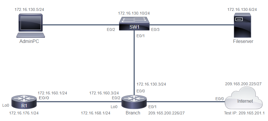
  172.16.130.0 =======> 172.16.10000010.00000000
  172.16.160.0 =======> 172.16.10100000.00000000

  Wild Card Mask = 00000000.00000000.00111111.11111111 = 0.0.63.255

  Permit 172.16.128.0 0.0.63.255 or
  Permit 172.16.130.0 0.0.63.255 or
  Permit 172.16.160.0 0.0.63.255 or
  Permit 172.16.176.0 0.0.63.255
  Branch> enable
  Branch# configure terminal
  Branch(config)# ip access-list standard NAT_Traffic
  Branch(config-std-nacl)# permit 172.16.160.0 0.0.63.255

  Branch(config)# interface ethernet 0/2
  Branch(config-if)# ip nat inside
  Branch(config)# interface ethernet 0/0
  Branch(config-if)# ip nat inside
  Branch(config)# interface ethernet 0/1
  Branch(config-if)# ip nat outside
  Branch(config)# exit

  Branch(config)# ip nat inside source list NAT_Traffic interface ethernet 0/1 overload

  AdminPC> enable
  AdminPC# ping 209.165.201.1  --> success

  FileServer# telnet 209.165.201.1 --> success
  Internet>exit
24. Introducing QoS
Converged Networks
- Converged network carry multiple types of traffic, such as voice, video, data, which were traditionally transported on separate and dedicated network
- Converged network have the following important traffic characteristics:
- Competition between constant, small-packet voice flows and bursty video and data flows
- Time-sensitive voice and video flows
- Critical traffic that must get priority
- Four major problems affect Quality on converged networks:
- Lack of Bandwidth capacity: multiple traffic compete for a limited amount of bandwidth and may require more bandwidth than is available.
- End-to-end Delay: variable dalay components(processing and queueing delay) and fixed delay component(serialization and propagatiion delay)
- Jitter: is the variation in latency or a disruption in the normal flow of packets as they transverse the network
- Packet Loss: caused by congestion, faulty connectivity, faulty network equipment.
- Different technique to manage quality issues:
- Increase the link capacity to accomodate the bandwidth requirements. Alternatively by utilizing a queueing technique to prioritize critical traffic or enabling a compression technique to reduce the number of bits that are transmitted for packets on the link.
- Dejitter buffer must buffer these packets and then play them out in a steady stream. If the ammount of jitter exceeds the dejitter buffer limits, the packet is dropped and the quality of the media stream is affected.
- Packet loss due to tail drop can be managed by increasing the link bandwidth, using a queuing technique, or by preventing congestion by sharping or dropping pakcets.
Introducing QoS
- QoS is the ability of the network to predictably provide business application with the service required for those applications to be successfully used on the network. (Consistent, Predictable, Performance)
- The goal is to have a better and more predictable network service with dedicated bandwidth, controlled jitter and latency, and improved loss characteristics as required by the business applications.
QoS Policy
- QoS Policy is QoS level that are assigned across a network and allow users to understand and negotiate for QoS in the network.
- Voice always first, Video always first after voice, Data best effort only when nothing else.
- Three basics steps in defining QoS Policies:
- Identify traffic and its requirements
- Group the traffic into classes with similar QoS requirements
- Define QoS policies that will meet the QoS requirements for each traffic class
-
Identify Network Traffic and Requirements
- Follow this step to identify network traffics:
- Network Audit by deploying classification tools such as NBAR, NetFlow, packet sniffers, etc.
- Business Audit to determine how the application requirements for each business unit maps into overall business model and goals.
- Service level Audit are reqired by different traffic classes in terms of delay and jitter requirements, packet loss tolerance, bandwidth that is required, and time sensitivity.
- Follow this step to identify network traffics:
-
Group Traffic into QoS Classes
- Enterprise define traffic classes as follow:
- Voice: absolute priority for VoIP traffic
- Mission-critical: small set of locally defined applications that are critical to the business
- Transactional and interactive: database access, transaction services, interactive traffic, and preferred data services
- Best-effort: Internet access and email
- Scavenger(less than best-effort) nonbusiness application such as p2p file sharing, straming video, and gaming site
- Enterprise define traffic classes as follow:
-
Define Policies for Traffic Classes
- Enterprise determine QoS policies:
- Voice: minimum bandwidth is 1Mbps, mark as priority 5 and LLQ
- Mission-critical and transactional: Minimum bandwidth is 5Mbps, mark as priority 4 and use CBWFQ
- Best-effort: max bandwidth 500kbps, mark as priority 2 and use CBWFQ
- Scavenger: max bandwidth 100kbps, mark as priority 0 and use CBWFQ
- Enterprise determine QoS policies:
QoS Mechanisms
-
Classification & Marking:
- classification determines which treatment that traffic should receive according to behavior and business policy.
- It’s the most fundamental QoS building block
- Traffic can be classified by various means
- Without classification, all packets are trrated the same
- Marking also known as coloring, based upon classiciation or metering so that other network devices have a mechanism of easily identifying the required treatment.
- classification determines which treatment that traffic should receive according to behavior and business policy.
-
Policing and Shaping: or rate-limiters is traffic conditioning mechanisms police traffic by dropping misbehaving traffic (excess traffic) to maintain network integrity or shape traffic to control bursts.
-
Policers:
- Are ideally placed as ingress tools (drop it as soon as possible so you don’t waste resources)
- Can be placed at egress to control the amount of traffic per class
- When traffic is exceeded, policer can either drop traffic or re-mark it
- Significant number of TCP re-sends can occur
- Doesn’t introduce jitter or delay
-
Shapers:
- Usually deployed between enterprise network and service provider to make sure that enterprise traffic is under contracted rate
- Fewer TCP-resends than policer
- Introduces delay and jitter
-
Policers:
-
Congestion Management: queueing mechanism to prioritize the transmission of packets based on the packet metering, normally implemented on all output interfaces. Congestions management includes:
-
Sheduling is a process of deciding which packet should be sent out next, scheduling occurs regardless of whether there is congestion on the link, if there is no congestion. Three example scheduling mechanisms:
- Strict priority lower priority are only served when the higher-priority queues are empty.
- Round-robbin: packets in queues are served in a set sequence.
- Weight fair: queues are weighted, so that some are served more frequently than others.
-
Queueing or buffering is te logice of ordering packets in output buffer. It’s only activated when congestion occurs. Queueing mechanism tools:
- FIFO is a single queue with packets that are sent in the exact order that they arrived.
- PQ is a set of four queues that are serverd in strict-priority order
- CQ is a set of 16 queues that are served in strict-priority order.
- QFQ is an algorithm that divides the interface bandwidth by the number of flows.
- CBWFQ (Class-based weighted fair queueing) : no latency guarantees, traffic classes get fair bandwidth guarantees
- LLQ (Low-latency queueing): adds a queue with strict priority
-
Sheduling is a process of deciding which packet should be sent out next, scheduling occurs regardless of whether there is congestion on the link, if there is no congestion. Three example scheduling mechanisms:
-
Congestion Avoidance: specific packet dropped early, based on marking, to avoid congestionm, typically implemented on output interfaces wherever a high-speed link or set of liunks feeds into a lower-speed link. tools for congestion avoidance:
- Tail drop : when a queue fills up, it drop packets as they arrive, it can result in waste of bandwidth if TCP traffic is predominant
-
Congestion avoidance : It drops random packets before a queue fills up, Cisco uses
WRED(drops packets randomly, but “randomness” is skewed by traffic weights)
-
Link Efficiency: mechanisms to improve bandwidth efficiency or the serialization delay impact of low speed links through compression and link fragmentation and interleaving. Link efficiency mechanisms are often deployed on WAN links to increase the throughput and to decrease delay and jitter. link efficiency mechanism includes:
- Layer2 payload compression (stacker, predictor, microsoft point-to-point compression)
- Header compression (TCP, real-time transport protocol (RTP), clas-based TCP, class-based RTP)
- LFI
QoS Models
-
Differentiated service model is a multiple-service model for implementing QoS in the network. Diffserv model have the following characteristics:
- It’s similar to a packet delivery services
- The network traffic is identified by class
- The network QoS policy enforces differentiated treatment of traffic classes
- You choose the level of service for each traffic class
- Diffserv major benefits:
- it’s highly scalable
- It provides many different levels of quality
- Diffserv major drowbacks:
- No absolute guarantee of service quality can be made
- It rquires a set of complex mechanisms to work in concert throughout the network
-
Diffserv terminology
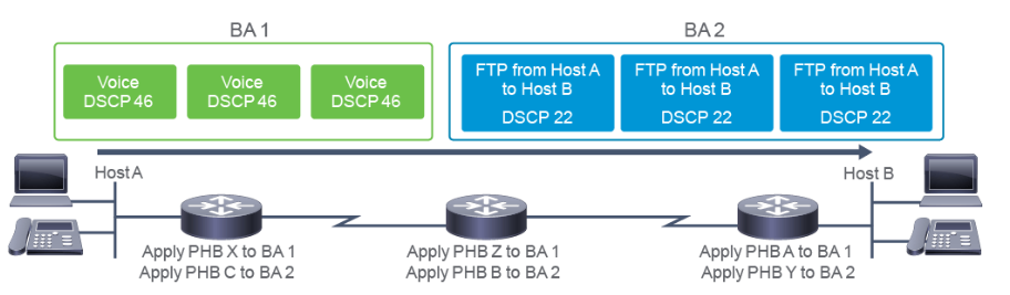
- DSCP is a value in the IP header that is used to select a QoS treatment for a packets.
- BA(behavior aggregate) is a collection of packets from multiple application with the same DSCP value crossing a link in a particular direction.
- PHB(Per-Hob Behavior) An externally observable forwarding behavior or QoS treatment that is applied at a DiffServ-complaint node to a DiffServ BA. Treatment such as packet scheduling, queuing, policing, or shaping behavior.
-
Per-Hop Behaviors
- Default PHB: tail drop, used for best-effort service
- Expendite Forwarding (EF): provides a mechanism to offer guaranteed bandwidth with the lowest delay, used for low-delay service
- Assured Forwarding (AF): provides a mechanism to provide different levels of forwarding assurances, used for guaranteed bandwidth service
- Class Selector: provides interoperability between DSCP-based and IP precedence-based devices in a network. Used for backward compatibility with non-DiffServ compliant devices.
Deploying End-to-End QoS
- A successful QoS deployment in Enterprise comprises multiple phases:
- Strategically defining QoS objectives
- Analyzing application service-level requirements
- Designing and testing QoS policies
- Implementing QoS policies
- Monitoring service levels to ensure business objectives are being met
- General guideline for implementing campus QoS:
- Classify and mark applications as close to their sources as technically and administratively feasible
- Police unwanted traffic flows as close to their sources as possible
- Always perform QoS in hardware rather than software when a choice exists
- Enable queuing policies at every node where the potential for congestion exists
- Protect the control plane and the data plane
25. Explaining Wireless Fundamentals
Wireless Technologies
- Wireless Personal Area network (WPAN) is a network that exists within a relatively small area and connects electronic devices, it can use bluetooth to connect.
- Wireless Local Area network (WLAN) provide more robust wireless network connectivity over a local area between an AP and associated clients. The goal is to connect to the backbone network.
- Wireless Metropolitan Area network (WMAN) is a wireless communications network that covers a large geographic area, such as city or a suburb.
WEireless Architectures
-
Ad Hoc Networks
- It creates an Independent basic service set (IBSS)
- It exists when two wireless devices communicate
- It contains a limited number of devices because of collision and organization issues
-
Wi-Fi direct is used to connect wireless devices for printing, sharing, syncing, and display.
- Wi-Fi direct in the enterprise
- Wi-Fi direct predefined services
-
Infrastructure Mode following are characteristics of infra mode:
- The AP functions as a translational bridge between 802.3 wired media and 802.11 wireless media
- Wireless is a hal-duplex environment
- A basic service area (BSA) is a wireless cell
- A BSS is the service that the AP provides
-
Service Set Identifier (SSID) network name used to roam between different APs within a network which the APs must share the same name.
- Broadcast vs hidden SSID
-
Centralized Wireless Architecture or split MAC is an architecture for the control and provisioning of wireless access point (CAPWAP), all MAC functionality that is not real time is processed by the WLC. it brings these features:
- Centralized tunneling of user traffic to the WLC (data plane and control plane)
- System-wide coordination for wireless channel and power assignment, rogue AP detection, asecurity attacks, interference, and roaming
- The AP only handle real-time functionality:
- Frame exchange handshake
- Transmission of beacon frames, which advertise all the nonhidden SSID
- Buffering and transmission of frames
- Providing real-time signal
- Monitoring all radio channels for noise
- Wireless encryption & decryption
- The WLC functionality:
- 802.11 authentication
- 802.11 association and reassociation (roaming)
- 802.11 frame translation and bridge to non-802.11 networks, such as 802.3
- Radio frequency (RF) management
- Security management
- QoS management
- APs in a centralized architecture have 2 modes:
- Local mode is when AP is operating in local mode, all user traffic is tunneled to the WLC, where VLANs are defined
- Flex connect is eliminate the need for WLC and client traffic may be switched locally on the AP instead of tunneled to the WLC
-
Control and Provisioning of Wireless Access Points (CAPWAP)
- CAPWAP is the current industry-standard open protocol for managing wireless APs and control messages are exchanged between the WLC and AP across an encrypted tunnel.
- CAPWAP tunnel use this UDP ports:
- control plane (UDP port number 5246)
- data plane (UDP port number 5247)
-
Mapping SSID to VLANs : need to isolate two frames for 2 different VLANs from each other on the cable because they were separated in the wireless space.
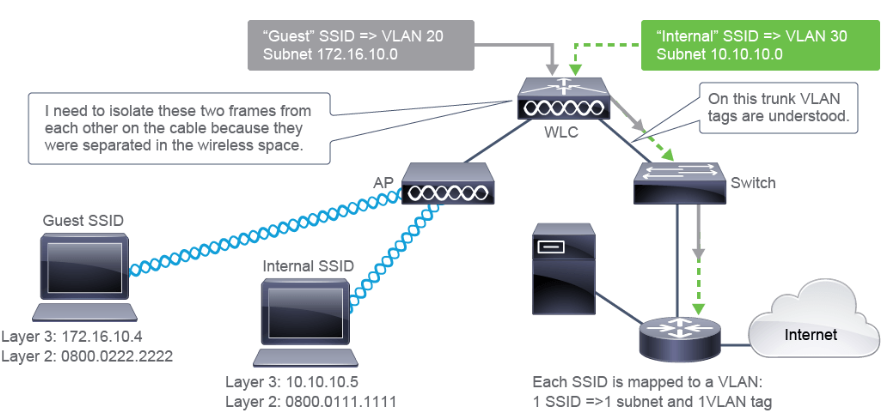
-
Switch VLAN configuration to support WLANs
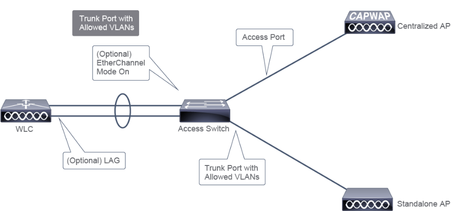
SW1# conf t SW1(config)# vlan 11 SW1(config-vlan)# name WLC_MANAGEMENT SW1(config-vlan)# vlan 12 SW1(config-vlan)# name AP SW1(config-vlan)# vlan 14 SW1(config-vlan)# name CORP -
Switch Port Connected to WLC Configuration
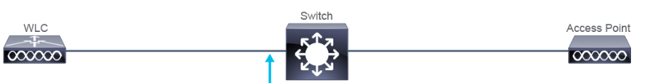
Configuration of the switch port connected to the WLC:
SW1# conf t SW1(config)# int Gi1/0/4 SW1(config-if)# desc WLC SW1(config-if)# switchport mode trunk SW1(config-if)# switchport trunk allowed vlan 11,12,14 -
Switch Port Connected to WLC-based AP configuration
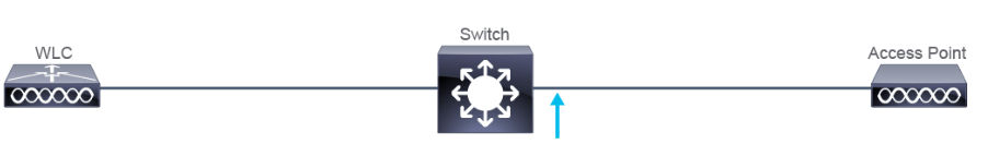
Configuration of the switch port connected to the AP:
SW1# conf t SW1(config)# int Gi1/0/2 SW1(config-if)# desc AP1 SW1(config-if)# switchport access vlan 12 SW1(config-if)# switchport mode access -
CAPWAP Communication
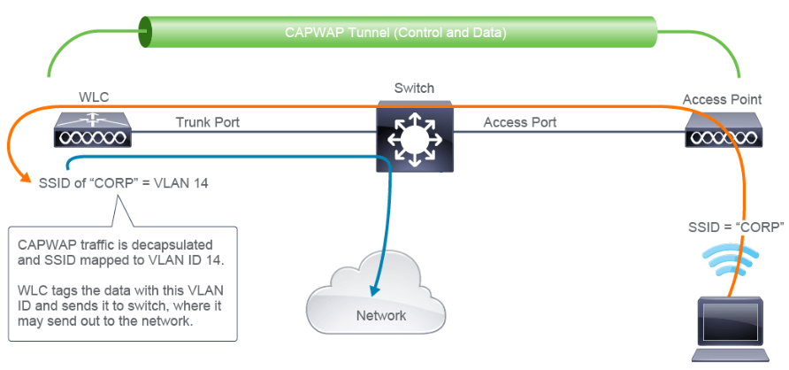
-
Switch Port Connected to Autonomous AP Configuration
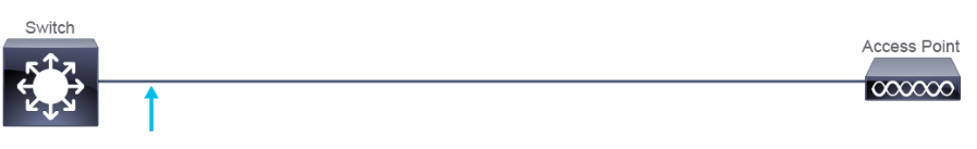
SW1# conf t SW1(config)# int Gi1/0/3 SW1(config-if)# desc AP2 SW1(config-if)# switchport mode trunk SW1(config-if)# switchport trunk native vlan 12 SW1(config-if)# switchport trunk allowed vlan 12,14 -
Autonomous AP Communication: Locally Switched
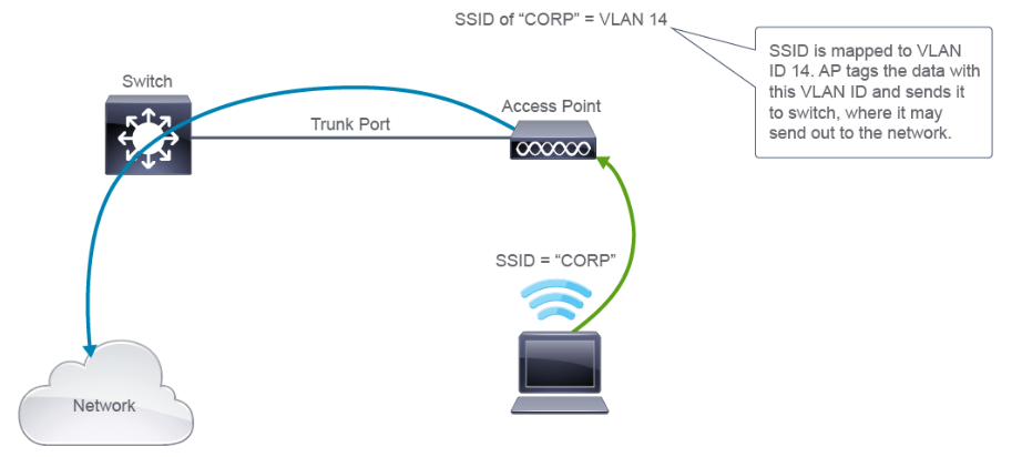
-
Workgroup Bridges is an AP that is configured to bridge between its Ethernet and wireless interfaces
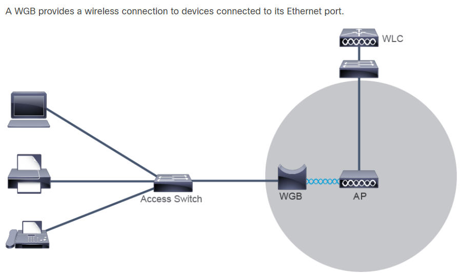
-
Mesh Networks
Mesh APs connect to the network using wireless:
- One APs radio is used to serve clients
- The second AP radio is used to backhaul traffic
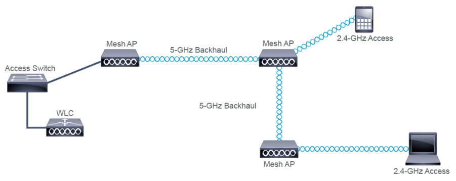
Wi-Fi Channels
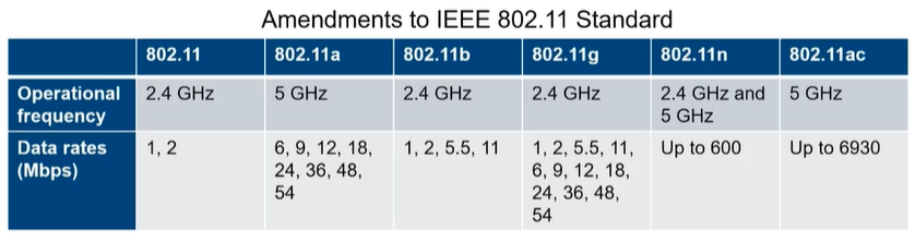
- The 2.4-GHz and 5-GHz radio bands are subdivided into multiple channels, where each AP uses one channel for its operation.
- Channels need to be non-overlapping
- Overlapping channels can cause
- Co-channel interference
- Adjacent channel interference
-
2.4 GHz Spectrum
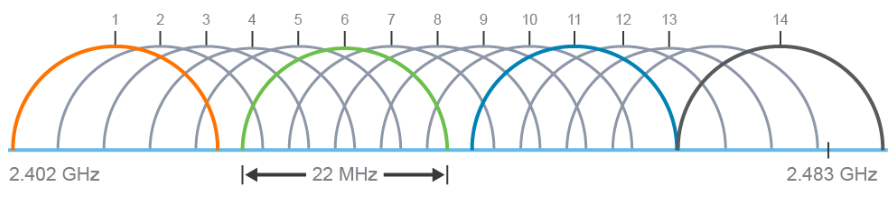
- Channels in the 2.4-GHz industrial, scientific, and medical (ISM) band are numbered from 1 to 14 (only to 11 in US, 13 in EU)
- Only three or four nonoverlapping channels are available
- 1,6,11 in US & EU
- 1,6,11,14 in Japan
- Channel overlap can be co-channel interference or adjacent-channel interference
-
5Ghz Spectrum
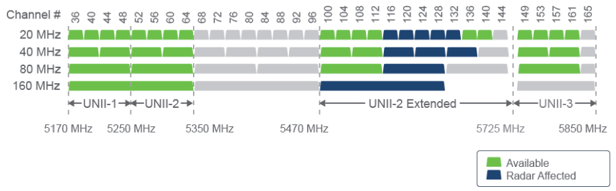
- Four UNII bands and one ISM band
- 25 channels available (one in ISM band) in US, 19 in EU
- Channel bonding is possible (40MHz, 80MHz, 160MHz channels)
-
2.4GHz & 5GHz Comparison
- 2.4GHz spectrum
- Advatages: Greater range & better propagation
- Disadvatages: More interference (WiFi & Non-WiFi) & not-enough channels
- 5GHz spectrum
- Advantages: Less crowded spectrum & More non-overlapping channels
- Disadvantages: Worse propagation & older devices don’t support it
- 2.4GHz spectrum
-
Other Non-802.11 Radio Interferers
- Microwave ovens
- Wireless Video Camera
- Flourescent Lights
- Motion Detectors
- Wireless Headphones
- Wireless Game Controller
AP and WLC Management WLAN Setup
-
Dynamic Host Configuration Protocol (DHCP) there are 2 ways of implementing DHCP:
- Using an internal DHCP server on the Cisco WLC (Internal WLC Server method)
- Uisng a switch or a router as a DHCP server (External WLC server Method)
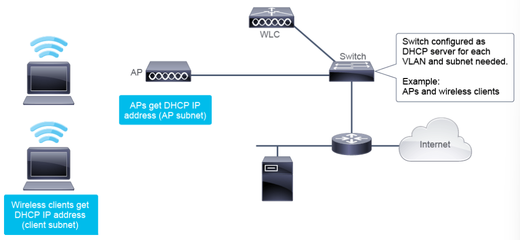
-
Domain Name System (DNS) An AP can use DNS during the boot process as a mechanism server. DNS discovery option mode operates as follows:
- The AP requests its IPv4 address from DHCP and includes options 6 for DNS Server IPv4 address and option 15 to get DNS information.
- IPv4 address of the DNS server is provided by DHCP server option 6
- The AP will use the information to perform a hotname lookup
- The AP will then be able to associate to responsive WLC by sending packets to the provided address
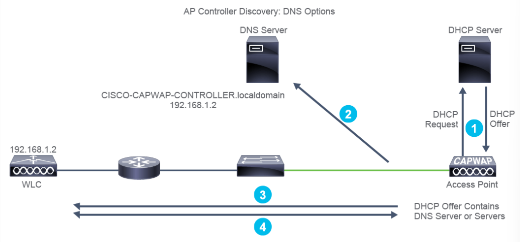
-
Network Time Protocol (NTP) to provides date/time synchronization for logs and scheduled events. it’s also used when a AP is joining a Cisco WLC to verify the creation and installation date of certificate on the AP, fail if wrong.
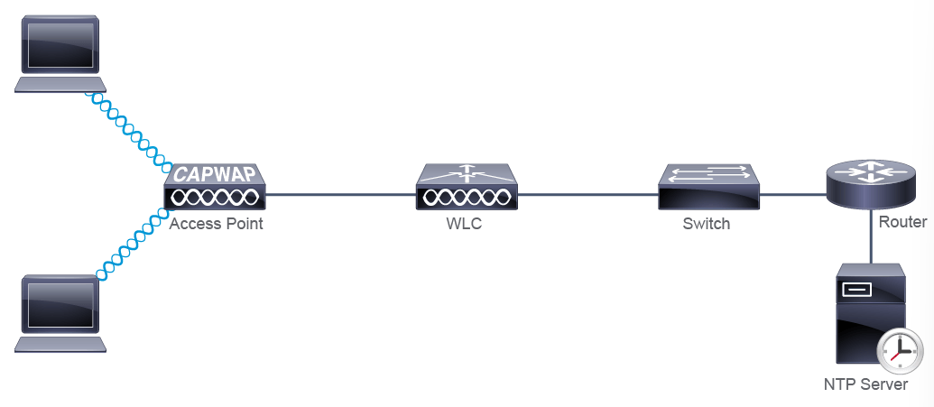
-
Authentication, Authorization, Accounting (AAA) to defines conditions by which access to the network is granted r refused. The AAA server functionality can be provided:
- Locally by a Cisco WLC
- Globally or centralized by an AAA server
- Management Protocol to control and view the status of the Cisco WLC from a remote management station. Example: Cisco DNA (Digital Network Architecture) Center
-
Command-Line Interface (CLI) can be used for normal configuration changes. WLC CLI is available via:
- Telnet (not secured)
- Secure Shell (SSH)
- Console Port
Management Console WLC
- How to login
- Open Browser > https://192.168.1.150 > Login
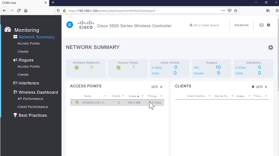
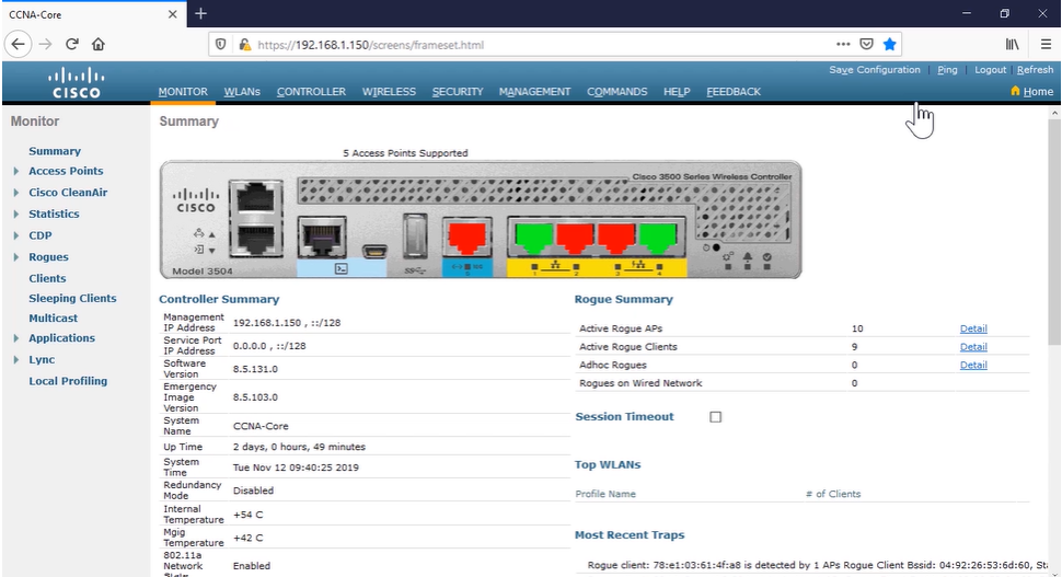
- Open Browser > https://192.168.1.150 > Login
- Monitor the WLC
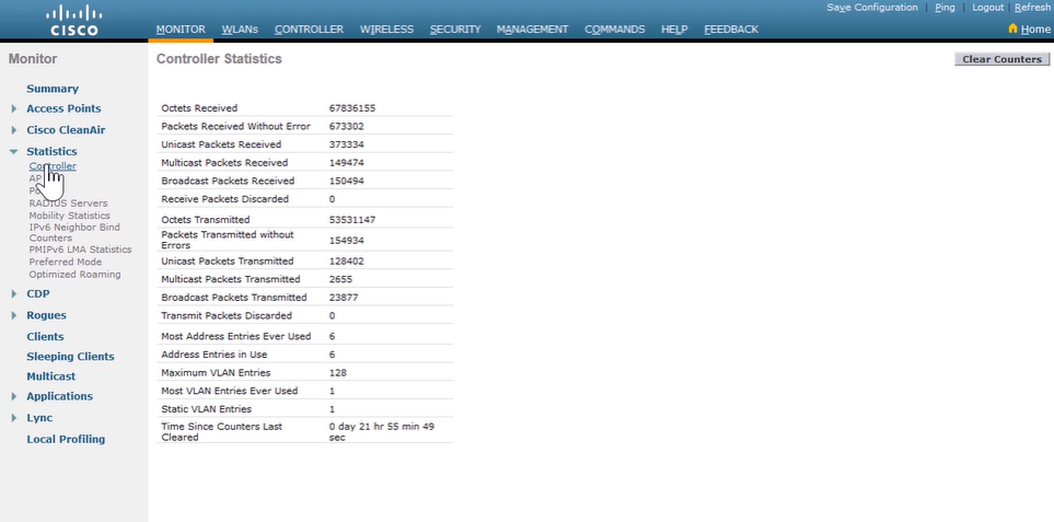
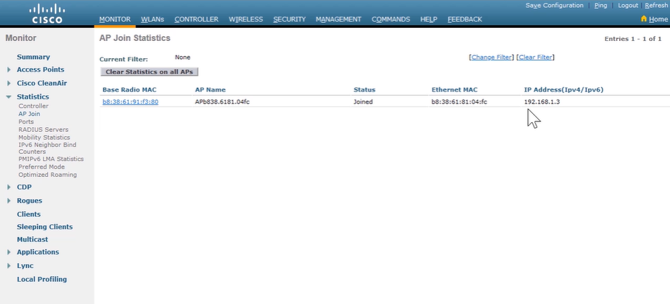
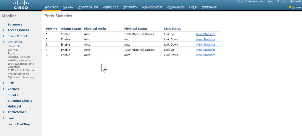
- Configure a Dynamic VLAN Interface
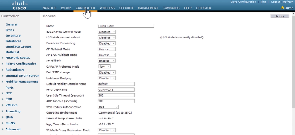
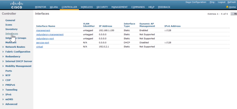
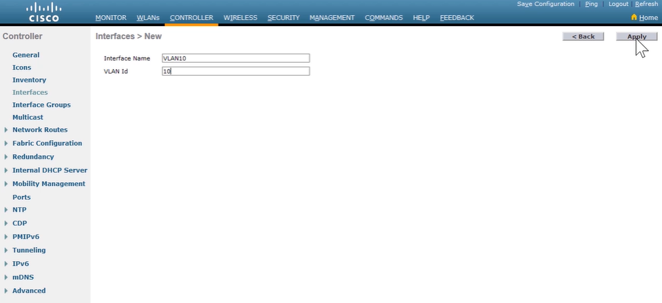
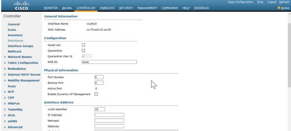
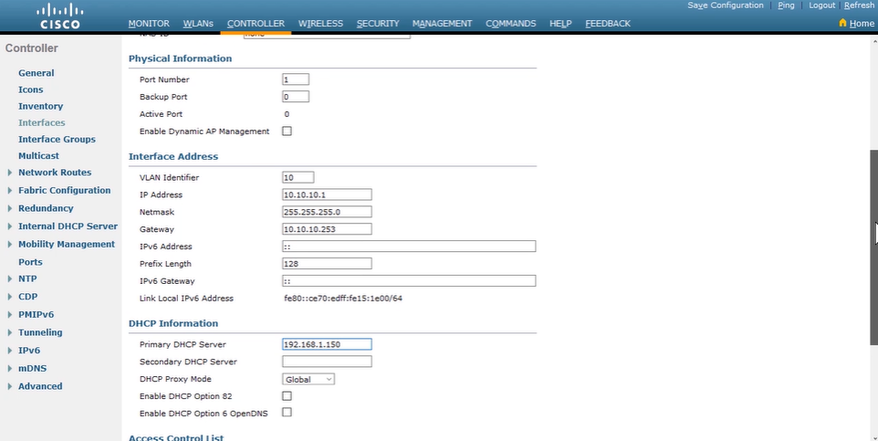
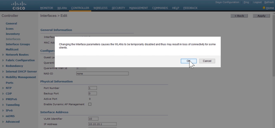
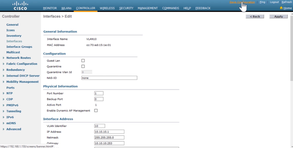
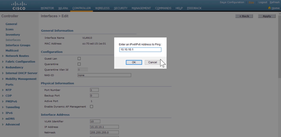
- Configure a DHCP Scope
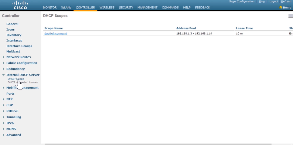
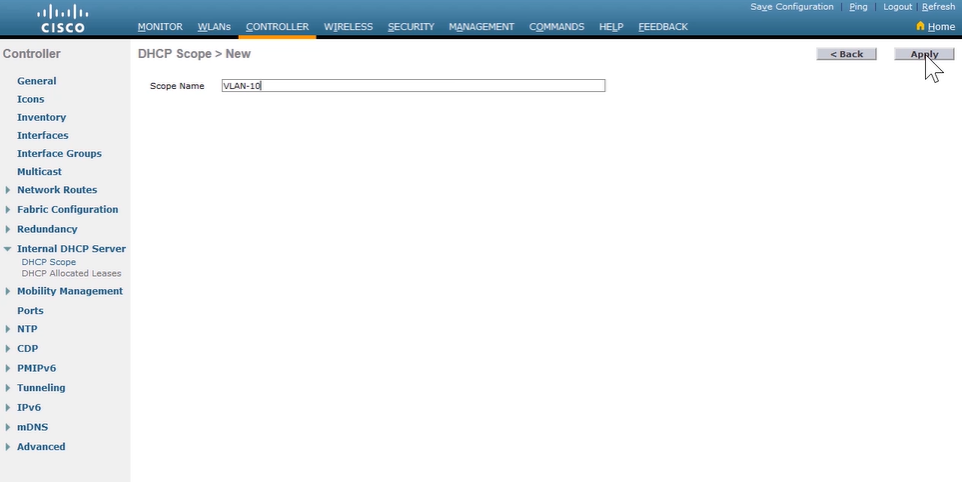
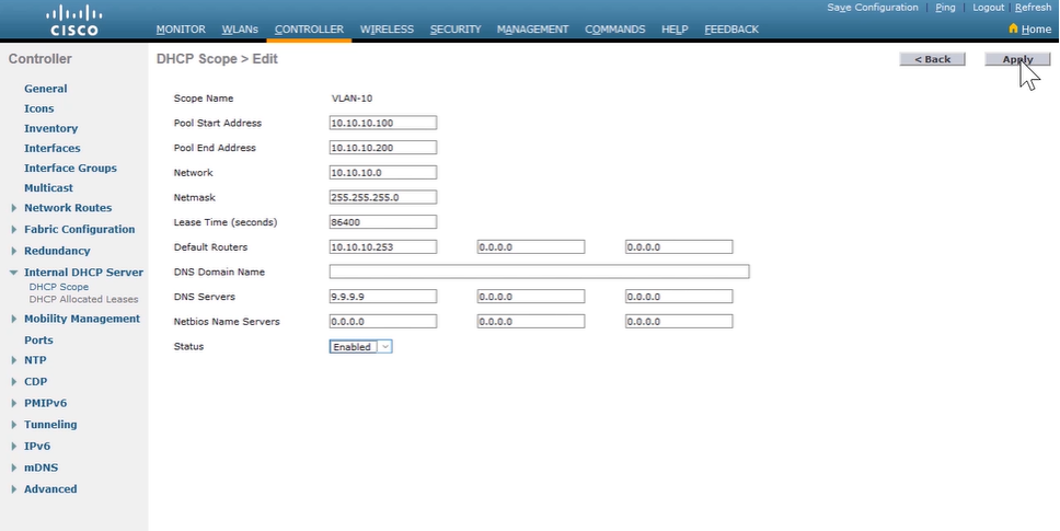
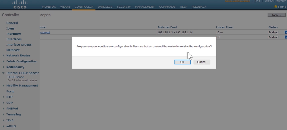
- Configure a WLAN
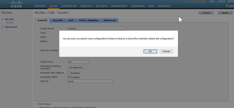
- Define a Radius Server
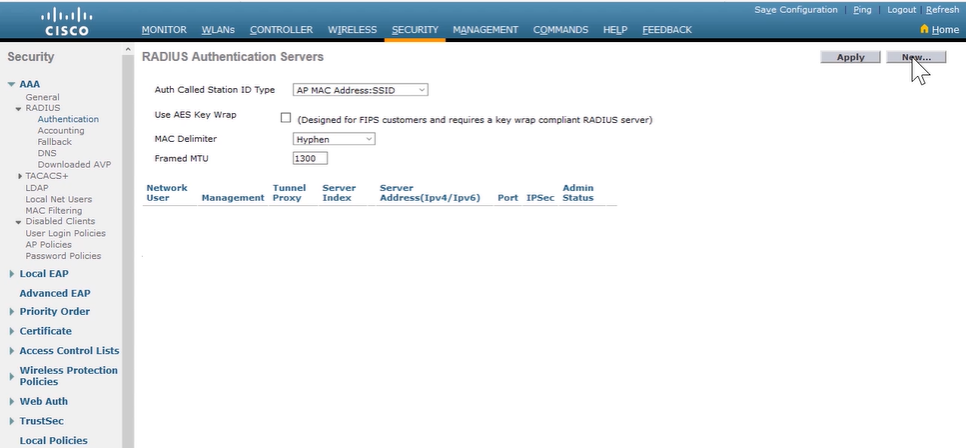
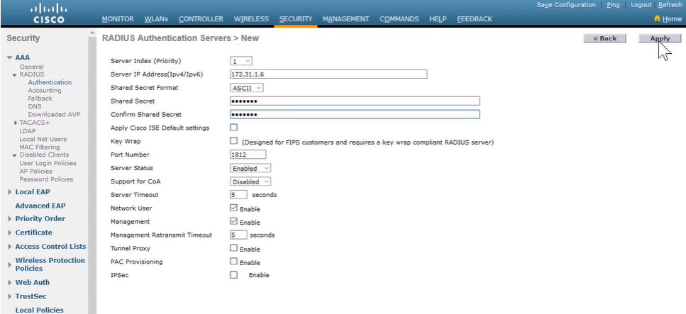
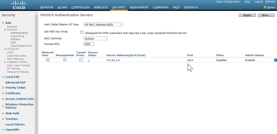
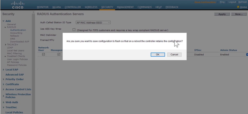
- Explore Management Options
26. Introducing Architectures and Virtualization
Introduction to Network Design
-
Principal objectives of network design
- Scalable network can expand quickly to support new users and applications without impacting performance of the service.
- Resilient network is both highly available and highly reliable which employ redundancy at multiple levels-device level, interlink level, software, and processes level.
- Security and QoS is a secure design that incorporate measure for physically securing the devices and measures to protect information. QoS requirements in mind controls how and when network resources are used by applications.
- Modular design approach addresses both scalability and resiliency, it’s facilitates implementation of services and helps in troubleshooting.
-
Tiered models proposed a hierarchical design and divide the network into discrete layers or tiers. Examples are the
three-tier hierarchicalandspine-and-leafmode
-
Issues in a poorly designed network
- Large broadcast domains: avoiding large failure domains involves clearly defining boundaries and also include a limited number of devices to minimize the negative effect of broadcasts.
- Management and support difficulties: because of disorganized, poorly documented, and lack easily identifiable traffic paths.
- Possible secuirty vulnerabilities: designed with little attention to security requirements at network access points can compromise the integrity of the entire network.
- Failure domains: failure in one network area can have a far-reaching effect if you don’t clearly define Layer2 and Layer3 boundaries.
Enterprise Three-Tier Hierarchical Network Design
- A tiered design brings these benefits:
- A tiered design allows you to better understand the features that may be needed
- A tiered design has stood the test of time, because it can be upgraded as technology changes and it evolves as needs grow.
- A tiered design makes it easy to discuss and learn about particular part of the solution.
- The modularity of tiered models is based on designing in layers, each with its own functionalities and devices.
- The hierarchical three-tier model includes:
-
Access Layer provides physical connection for devices to access the network. The are several functions, including network access control:
- Port security and VLANs
- Access control lists (ACLs)
- DHCP snooping
- Address Resolution Protocol (ARP) inspection
- QoS classification and marking
- Support for multicast delivery, Power over Ethernet (PoE), and auxiliary VLANs for VoIP
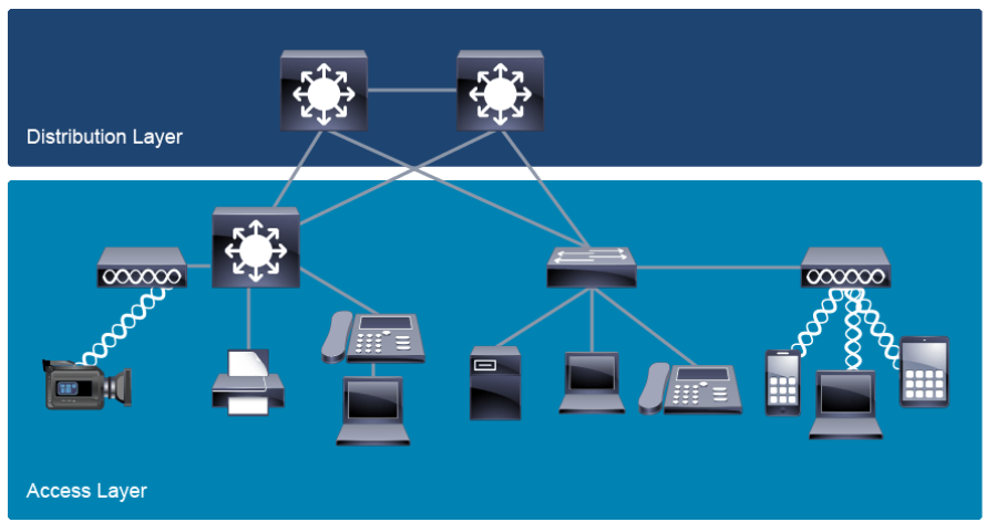
-
Distribution Layer is designed to aggregate traffic from the access layer and it’s appropriate for applying policies, such as QoS, routing, or security policies. There are several functions:
- aggregate access layer to core layer above
- perform packet manipulation, routing decision-making, and filtering to implement policy-based connectivity & QoS
- offer a default route to access layer routers and runs dynamic routing protocols
- to segment the network and isolate network problems, preventing these problem from affecting the core layer and other access network segment.
- used to implements policies regarding QoS, security, traffic loading, and routing.
- It’s provide gateway redundancy (FHRP, HSRP, VRRP, GLBP)
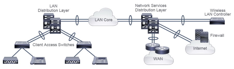
-
Core Layer provides fast transport between distribution layer devices and it’s an aggregation point for the rest of the network, it’s provides high-speed packet forwarding and redundancy. The function are:
- binds together all distribution networks and provides fast packet transport
- To provide scalability to minimize the risk from failures while simplifying moves, adds, and changes in the campus.
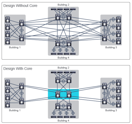
-
Access Layer provides physical connection for devices to access the network. The are several functions, including network access control:
Spine-Leaf Network Design
-
Spine-leaf is a two-tier architecture that resembles Cisco’s original collapsed core design when using the three-tier approach. Leaf-layer is connected to each of the top-tier switches (spine leaf) in a full-mesh topology.
- Leaf Layer consist of access switches that connect to servers
- Spine Layer is the backbone of the network and is responsible for interconnecting all leaf switches
- if device port capacity becomes a concern, a new leaf switch can be added by connecting it to every spine switch.
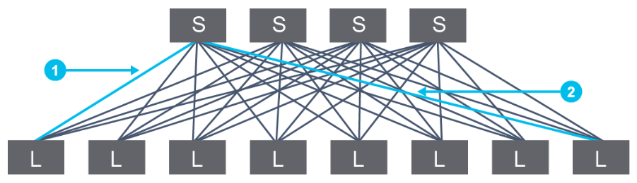
- The spine-leaf design has additional benefits:
- Increased scale within the spine to create equal-cost multipaths from leaf to spine
- Support for higher performance switches and higher speed links
- Reduced network congestion by isolating traffic and VLANs on a leaf-by-leaf basis
- Optimization and control of east-west traffic flows
Cisco Enterprise Architecture Model
- Network services, such as security and QoS, are also implemented on a modular basis.
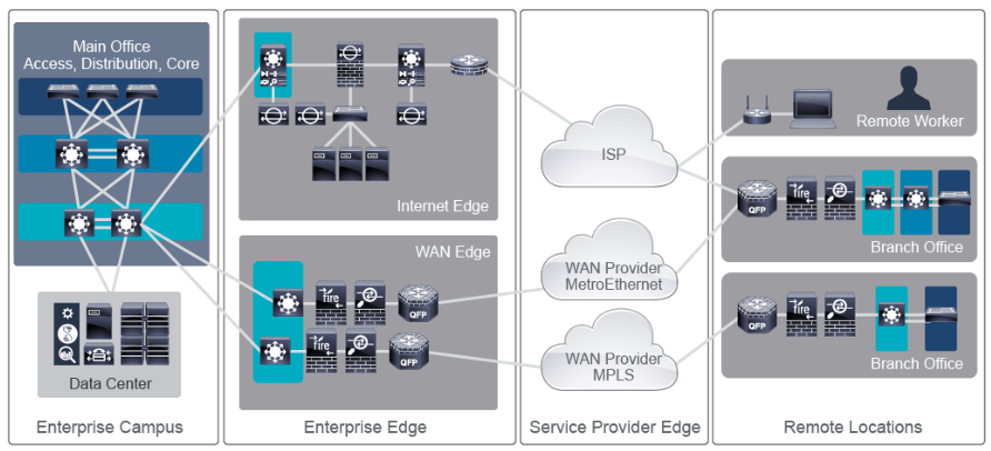
- The following modules make up the Cisco Enterprise Architecture:
-
Enterprise Campus
- The enterprise campus module follows the three-tier architecture with access, distribution, and core tiers, but includes network services, normally inside a data center submodule.
- Inside the data center submodule, the architecture is spine-leaf.
- Enterprise Edge provides the connectivity outside the enterprise and often functions as an intermediary between the enterprise campus module, to which it connects via its core, and other modules.
- Service Provider Edge provides connectivity between the enterprise main site and its remote locations.
- Remote Locations that represents geographically distant parts of the enterprise network.
-
Enterprise Campus
Cloud Computing Overview
- Clouds characteristics:
- On-demand self-service server computing time and network storage are activeted as needed without requiring human interaction with each cloud provider.
- Broad network access are accessible to the user remotely and can be accessed by using a variety client platforms (mobile, tablets, laptop etc)
- Resource pooling backup and data management are centralized, and user can move from one device to another.
- Rapid elasticity users can scale reources on their own and optimize the resources to reduce costs.
- Measured service use metering to monitor and control resource usage.
- Outsourcing computing resources to the cloud can be a solution for:
- For an enterprise taht don’t have the in-house expertise to effectively manage their current and future IT infrastructure
- For large enterprises where resources are shared by many users or organizational units
- For enterprises in which computing resource needs might increase on an ad hoc basis and for a short term.
- For enterprises that decide to outsource only part of their resources (web front-end).
- Cloud deployment models:
- Public clouds are open to use by general public and managed by a dedicated cloud service provider.
- Private clouds is lack of public access and it’s owned, managed and operated by a third party, or the user itself.
- Community cloud is an infrastructure intended for users from specific organizations that have common business-specific objectives or work on joint projects and have the same requirements for security, privacy, performance, compliance, and so on. It can be managed internally or by a third party and it may exist on or off premises.
-
Hybrid cloud is the cloud infrastructure that is a composition of two or more distinct cloud infrastructures, such as private, community, and public cloud.
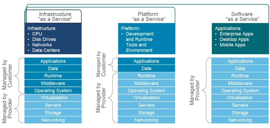
- Three NIST-defined service models:
- Infrastructure as a Service (IaaS) clouds offer pure computing, storage, and network resources. Example: Amazon Elastic Computing Cloud, Microsoft Azure Virtual Machines, Google Compute Engine, Oracle Compute Cloud Services, IBM Cloud Virtual Servers.
- Platform as a Services (PaaS) model offers a software platform with everything required to support the complete life cycle of building and delivering applications. Example: Google App Engine, Salesforce, Heroku, Oracle Cloud Platform.
- Software as a Service (SaaS) is also called a hosted software model, and includes ready-to-use applications or software with all the required infrastructure elements required for running them, such as OS, DB, and network. Example Cisco Webex, Salesforce, Microsoft365, Adobe Creative Cloud.
- Anything as a Services (XaaS) is a concept that emphasizes that the cloud offer can include any computing service. Example: Cisco DaaS, Microsoft Azure SQL Database, Amazon Relational Database Service, Google Function.
Network Device Architecture
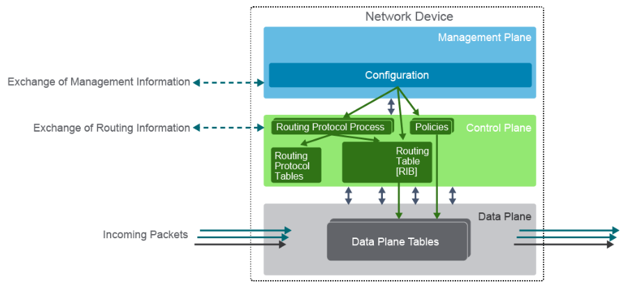
- Network devices implement 3 different processes:
- Data Plane also called the forwarding plane, is responsible for the high-speed forwarding of data through a network device. Example of Data Plane structures are Content Addressable Memory (CAM) table, Ternary CAM (TCAM) table, and Forwarding Information Base (FIB) table, and Adjacency table.
-
Control Plane consist of protocols and processes that communicate between network devices to determine how data is to be forwarded. It’s responsible for building the routing table or Routing information Base (RIB).
- In Layer2 devices, the control plane processes information from Layer2 Control protocols (STP, CDP)
- There are 2 types of process switched traffic:
- directed/addressed to the device itself and must be handled directly by the device processor. example: routing protocol data exchange
- data plane traffic with a destination beyond the device itself, but which requires special processing by the device processor. Example: IPv4 packets that have TTL value, IPv6 that have a Hop Limit value.
-
Management Plane consist of functions that achieve the management goals of the network, which include interactive configuration sessions, and statistics gathering and monitoring. It’s used to manage a device through its connection to the network. The management plane is associated with traffic related to the management of the network or the device and it’s encompasses applications and protocols such as SSH, SNMP, HTTP, HTTPs, NTP, TFTP, FTP, etc.
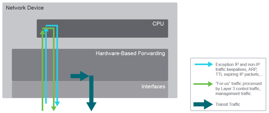 There are three general types of packets:
- Transit Packets and Frames include packets and frames that are subjected to standard, destination IP, and MAC-based forwarding functions. It’s typically forwarded with minimal CPU involvement or within specialized high-speed forwarding hardware.
- Receive or for-us packets include control plane and management plane packets that are destined for the network device itself. They are ultimately destined for and handled by applications running at the process level within the device operating system.
-
Exception IP and Non-IP information include IP packets that differ from standard IP packets, such as IPv4 packets containing the Options field in the IPv4 header.
Virtualization Fundamentals
- Prior to virtualization, data centers and server farms consisted of multiple, clustered physical servers that provided necessary redundancy for stable operation of applications.
- The virtualization software is known as a hypervisor, it’s divides physical hardware resources in software and allocates them to create multiple VM Instances.
- A hypervisor has this tasks:
- Providing an operating platform to VMs
- Managing the execution of the guest operating system
- Providing connectivity between VMs and between the VMs and external network resources
- There are two types of full virtualization:
- the hypervisor is running directly on the physical server hardware(native, bare-metal, type1 hypervisor)
- The hypervisor runs on a host operating system (type2 hypervisor). Example are VMware ESXi and VMWare workstation, Microsoft Hyper-V, and Microsoft Virtual PC, Citrix XenServer, Oracle VM, and Oracle Virtual Box, Redhat Enterprise Virtualization.
- VM benefits over physical devices:
- Partitioning: more efficient use of resources and hypervisor divides host system resources between VM and allows VM provisioning and management
- Isolation: have as much security as is present in traditinal physical server environments. VM that share the same host are completely isolated from each other, but can communicate over the network. Affected VM can be easily and automatically migrated to other hosts in the virtual infrastructure.
- Encapsulation: are simply to back up, modify, or even duplicate. VM reside in a set of files that describe them and define thier resource usage and unique identifier.
- Hardware Abstraction: Can be provisioned or migrated to any other physical server that has similar characteristics. support in multiple OS (windows, linux, so on) and broader support for hardware.
- VM beneficial for these reasons:
- Optimum Performance: easily to moved to another host that has sufficient resources
- Maintenance: during maintenance, VMs can be temporarily redistributed to other hosts.
-
Resource Optimization: the hosts that are emptied can be powered off to reduce cooling and power requirements.
-
Container are made possible using kernel features of the host OS and a layered file system instead of the emulation layer required to run VMs. Containerized applications can consist of smaller containerized components instead of legacy monilithic applications installed on a virtual or bare metal system. One popular platforms is Docker, it’s a management system that is used to create, manage, and monitor Linux containers, Ansible is another container-management system favored by RedHat.
-
Virtualization of Networking Functions one physical device can be segmented into several devices that function independently and network devices interface can be logically divided into subinterfaces. VLANs are a virtual element mostly related to Layer2 switches. A Switch Virtual Interface (SVI) is another virtualization element in Layer2 devices which a virtual interface that can have multiple physical ports associated with it. With VRF, routing and related forwarding information is separated from other VRFs. Each VFR contains a separate address space, and makes routing decisions that are independent of any other VRF layer3 interface, logical, or physical.
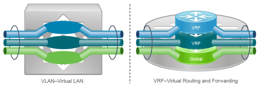
27. Explaining the Evolution of Intelligent Networks
Overview of Network Programmability in Enterprise Network
-
Current Industry Trends
- DevOps: is a methodology that strives to develop and promote methods to drive speed and agility in the deployment, maintenance, and continual improvement of systems and infrastructure. Examples tools that are used by a DevOps culture to enable a robust deployment pipeline including Linux OS, programming language (Python, Go, Ruby etc), config management (Ansible, SaltStack, Chef, Puppet), CICD (jenkins, Travis CI), version control (Git).
-
Prgrammable Infrastructure: Two form of network programmability
- On-box programming refers to scripting mechanisms such as the Tool Command Language (TCL) and Embedded event manager.
- Off-box programming refers to scripting mechanisms that exist outside the network device, it can be external server that often communicates to network device using APIs, example NETCONF, REST, RESTCONF
- Open Source Software: refers to community-driven model of developing and maintaining software to increase flexibility and customizability, while lowering the capital expense required. A typical example is usage of Linux Software on many network devices which means almost always using off-box methods for network programability.
- Software-defined networking: refers to the set of techniques that are used to manage and change network behavior through an open interface rather than closed-box methods. Example are disaggregation of network devices control and data plane.
- Intent Based Networking: transforms a hardware-centric, manual network into a controller-led network that captures business intent and translates it into policies that can be automated and applied consistently across the network.
-
Overview of Network Operations in an Enterprise Network
- Current Network operations:
- CLI was built for manual interactions
- Configuration is one device at a time
- Copying and pasting are the standard
- Configuration is prone to error
- Tasks are not easily repeatable
- Notepad is the most common text editor
- Future Network operations:
- Programmability tools will be used to automate
- Version control will be used for all configuration and monitoring changes
- Automated systems will perform testing before any changes is made to the config including system, style, reachability
- Using notepad or text editor will prone to error, because:
- CLI was design for human interaction, limiting the speed of config
- Manual configuration and common copying and pasting methods are extremely prone to error
- Tasks are not easily repeatable, resulting in inefficient workflows
- Unstructured text data used in the CLI requires postprocessing to transcode to machine-friendly formating
- Current Network operations:
-
Uses of Network Automation is used for many common tasks:
- Device provisioning: is simpley configuring network deviecs more efficiently, faster and with fewer error.
- Device software management: controlling the download and deployment of software updates is a relatively simple task, but it can be time-consuming and prone to error.
- Data collection and telemetry: that data is collected is changing as many devices can push data off-box in real time in contrast to being polled every few minutes.
- Compliance checks: allow the unique ability to quickly audit large groups of network devices for configuration errors and automatically make the appropriate corrections with built-in regression test.
- Reporting: decrease the manual effort to extract information and coordinate data from disparate information sources in order to create meaningful reports.
- Troubleshooting: makes troubleshooting easier by making configuration analysis and real-time checking very fast and simple.
-
Network Programmability Technology such as:
- Linux: the foundation of everything from version control to programming language and config management (Ansible, Puppet)
- Device and controller API: is the mechanism by which an end user makes a request of a network device and reponds back to users.
- Version Control: Use git to make easier to share and collaborate on projects involving anything from code to config file. All network config info should be versioned.
- Software Development: understanding software development processes is critical to understanding how software development can be used to extend or customize open source tools.
- Automated Testing: Deploying proper testing, such as pre- and post- changes on the network in an automated way improves the use of network resources.
- Continuous Integration (CI): CI tools are used commonly by developers and can drastically improve the release cycle of software and network config changes.
-
Network Programmability Options
- The are different network programmability options available today:
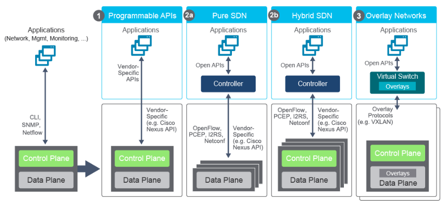
- Opt1. the control and data planes are still in the same box as in traditional approach. Example NX-API interface that is used in Switches. Later, open APIs (NETCONF, RESTCONF) added to vendor-specific APIs.
- Opt2a. shows pure SD environment where control plane has been separated to a controller. OpenFlow was the first protocol for communication, NETCONF is one of the config protocols and others PCEP, I2RS
- Opt2b. A control plane is still needed on the network devices independently run some network protocol (routing). Also the controller uses an abstraction layer
- Opt3. represents an overlay approach, which use VXLAN protocol.
- The are different network programmability options available today:
Software-Defined Networking
- What is software-defined networking? is a set of techniques, not necessarily a specific technology, that seeks to program network devices either through a controller or some other external mechanism.
- An approach and architecture in networking where control and data planes are decoupled, and intelligence and state are logically centralized
- An implementation where the underlying network infrastructure is abstracted from the applications (via network virtualization)
- A concept that leverages programmatic interfaces to enable external systems to influence network provisioning, control, and operations
- SDN addresses the need for the following:
- Centralized configuration, management, control and monitoring of network devices
- The ability to override traditional forwarding algorithms to suit unique business or technical needs
- Allowing external applications or systems to influence network provisioning and operation
- Rapid and scalable deployment of network services with lifecycle management
-
Traditional vs Software-Defined Networks
- In traditional Network:
- The data/forwarding plane is responsible for forwarding of data through a network device and acts on the forwarding decisions
- The control plane is responsible for controlling the forwarding tables taht the data plane uses.
- The management plane is integrated into the control plane
- In control and management planes learn/compute forwarding decisions
- All traditional devices are equally smart and can make decisions on their own
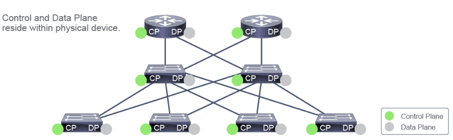
- In Software-defined network:
- The control and management plane becomes centralized and acts independently
- Physical devices reatin data plane functions only
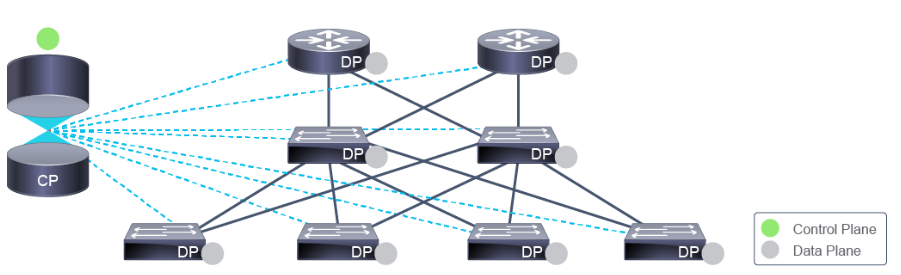
- In hybrid-SDN:
- A controller is centralized and separated from the physical device, but devices still retain localized control plane inteligence
- hybrid SDN is a combination of the best of both schemes.
- The SDN Controller has the ability to act as the brain of the network.
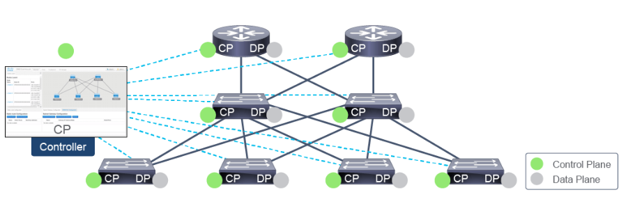
- In traditional Network:
-
SDN Layers it comprises three stacked layers:
- Infrastructure Layer: Contains network elements (any physical or virtual device that deals with traffic)
- Control Layer: Represents the core layer of the SDN Architecture. It contains SDN controllers, which provide centralized control of the devices in the data plane. It use southbound APIs to control individual devices in the infrastructure layer. And use nothbound APIs to provide abstracted network view to upstream applications.
-
Application Layer: contains the SDN applications, which communicate network requirements towards the controller.
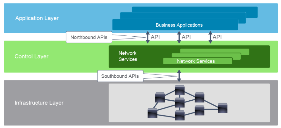
-
Northbound and Southbound APIs
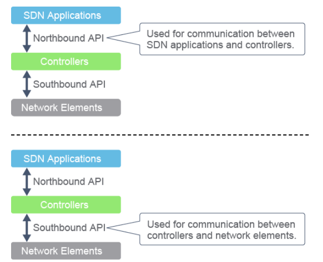
-
Northbound APIs are responisble for the communication between the SDN controller and the services that run over the network. Currently
REST APIis predominately being used as a single northbound interface that you can use for communication between the controller and all applications.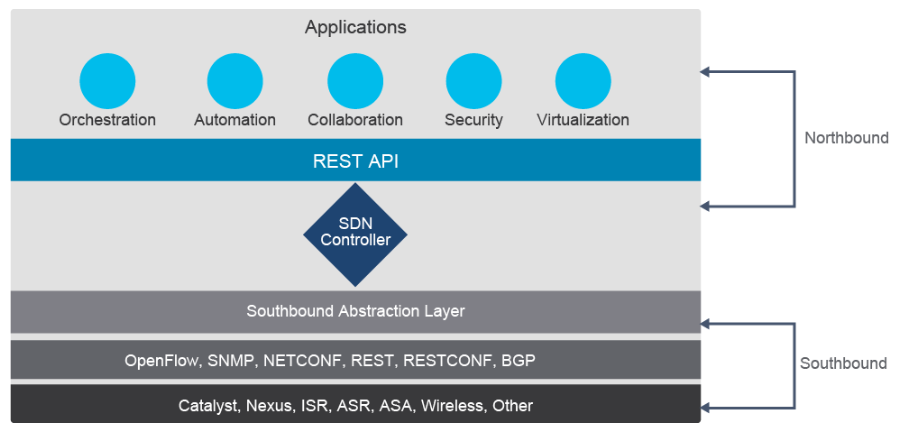
-
Southbound Abstraction Layer allow you to have one single place where you start writing the applications to and allow application policies to be translated from an application through the APIs, using whichever southbound protocol is supported and available on the controller and device. Below is the southbound protocols and APIs:
- OpenFlow: allows direct access to and manipulation of the forwarding plane/table of network devices such as switches and routers. The actual configuration of the devices is by the NETCONF.
- NETCONF: provides mechanisms to install, manipulate, and delete the configuration of network devices via Remote Procedure Call mechanisms and messages are encoded in XML. it’s a dominant protocol that allows you to modify the config of a network devices.
- RESTCONF: it’s adds a REST API to NETCONF
- OpFlex: an open-standard protocol that provides a distribution control system that is based on a declarative policy information model. OpFlow uses an imperative SDN model where a centralized controller sends detailed and complex instructions to the control plane of the network elements to implement new application policy. OpFlex uses a declarative SDN model, which the controller name is Cisco Application Policy Infrastructure Controller (APIC), sends a more abstract policy to the network elements.
- REST: allows controllers to monitor and manage infrastructure through the HTTP and HTTPS protocols, with the same HTTP verbs that Web browsers use to retieve web pages.
- SNMP: is used to communicate management information between the network management stations and the agents in the network elements.
- Vendor-specific protocols: vendors use their own proprietary solutions, which provide REST API to a device, example: NX-API for Cisco Nexus family. Common Programmability Protocols and Methods
-
Northbound APIs are responisble for the communication between the SDN controller and the services that run over the network. Currently
- Evolution of Network Configuration
-
Evolution of Device Management and Programmability
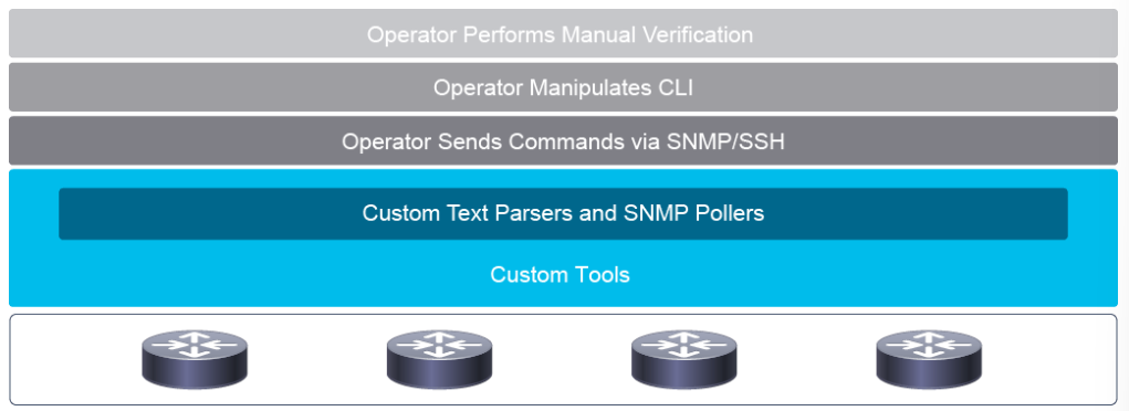
- One of the most SNMP weaknesses from the network programmability perspective is that SNMP lacks libraries for various programming languages.
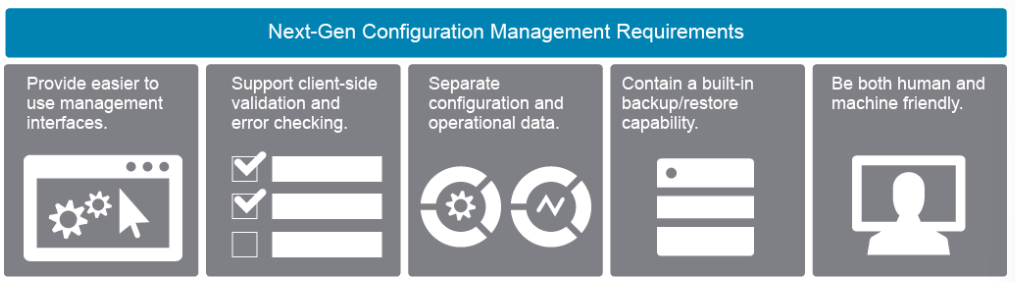
- The requirements for next-gen config management:
- Provide easier to use management interfaces: it should be able to leverage custom and open source tools to easily consume the APIs.
- Support client-side validation and error checking: the management that leverage the device API and model automatically to do error checking and validation.
- Separate configuration and operational data: any attribute, config parameter, or statisti be accessible via the API.
- Contain a built-in backup and restore capability: making simpler to perform backups and restores, but also to improve how changes are made.
- Be both human and machine-friendly: having APIs that support readable data formats such as JSON and XML.
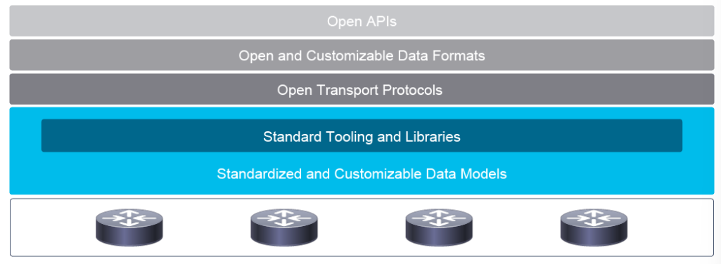
- Key attributes for next-gen programmatic interface:
- They must support different types of transport: HTTP, SSH, Transport Layer Security
- They must be flexible and support different types of data encoding formats: XML and JSON
- They must be efficient and easy-to-use tooling that helps in using the new APIs: Programming libraries (SDKs)
- They must be extensible and open APIs: REST, RESTCONF, NETCONF, gRPCs.
- They must be model-driven: helps any transport, API, encoding, and data format.
- One of the most SNMP weaknesses from the network programmability perspective is that SNMP lacks libraries for various programming languages.
-
Model-Driven Programmability
- Model-driven programmability of Cisco devices allows you to automate the configuration and control of those devices or even use orchestrators to provide end-to-end service delivery (Cloud computing).
- Data modeling proves a programmatic and standards-based method of writing configurations to network devices, replacing the process of manual configuration.
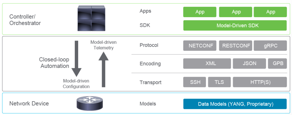
- The core component of the complete device API include:
- Data Models: defines the syntax and semantics, including constraints of working with the API, it use a standard representation data from the network device for the device configuration.
- Transport: Model-driven APIs support one or more transport methods including SSH, TLS, and HTTP(s).
- Encoding: Data can be encoded in JSON, XML, Google Protocol Buffers (GPB) format. Programmability infrastructure is designed to support different encoding of the same data model if the transport protocol support it.
- Protocols: there are three core protocols: NETCONF, RESTCONF, and gRPC protocols. Protocol choice will ultimately be influenced by the networking, programming, and automation background, plus available tooling.
- SDK is set of tools and software lbraries that allows an end user to create their own custom applications for various purposes, including managing hardaware platforms.
- The process of automating configurations and monitoring in a network involves the use of core components:
- Client Application: manages and configurations and monitors the devices in the network.
- Network Device: Acts as a server, responds to requests from client application, and configures the devices in the network.
- Data Model (YANG) module: describes configuration and operational data of the network device, and performs actions.
- Communication Protocol: provides mechanisms to install, manipulate, and delete the configuration of network devices.
- Telemetry is an automated communcations process by which measurements and other data are collected at remote or inaccessible points and transmitted to receiving equipment for monitoring. Model driven telemetry provides a mechanism to stream data from a model-driven telemetry-capable device to a destination. Model-driven telemetry is a new approach for network monitoring in which data is streamed from network devices continuously using a push model and provides near real-time access to operational statistics.
-
Data Models
- What is data model?
- Data models describe a constrained set of data in the form of schema language
- They use well-defined parameters to standardize the represntation of data from a network device
- They are not used to actually send information to devices, but instead they rely on protocols to send encoded documents that simply adhere to a given model.
- Device configuration can be validated against a data model in order to check if the changes are valid for the device before commiting the changes.
- Data model are used to describe the syntax and semantics of working with specific data objects.
- Data modelf provide a well-defined hierarchy of configurational and operational data of a router, and action that can be perform by a protocol:
- Configuration data: example config IP routing tables, config interface MTU, config eth interface
- Operational state data: example entries obtained from OSPF, attributes of the network interfaces
- Actions: set of actions that support robust networkwide config transactions.
-
YANG Data Models: is data modeling language that used to create device configuration request pr requests for operational data.
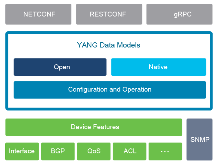
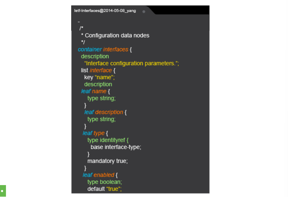
- What is data model?
-
Encoding Formats: used for applications to communicate with a wide range of APIs available on the internet. Common characterstics of API encoding: Format syntax, concept of an object, key/value notation, array or list, importance of whitespaces, case sensitivity.
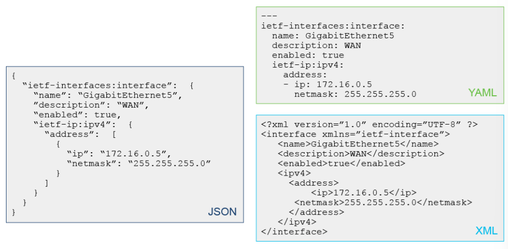
- XML Overview is a markup format that is human-readble, while enabling computers to efficiently parse the information and created to structure, store, and transport information.
- JSON is lightweight data format that is used in web services for transmitting data and it’s widely used in scripting-based platforms because of its simple format, it’s better for object-oriented systems.
- JSON Data Types uses a six data types: string, number, boolean, null, object, array.
- Namespaces define the syntax and semantics of a name element, and in that way avoid element name conflicts.
-
Protocols used to manipulate and automate on the data models supported on a network device.
-
Representational State Transfer (REST) is an architectural syles (versus a protocol) for designing network applications. REST uses a stateless clint-server model that typically uses HTTP(s) to make calls between entities, where resource representations are identified by a URL. REST support CRUD operations by using specific HTTP verbs. Several tools to test REST APIs: cURL, Postman, Python
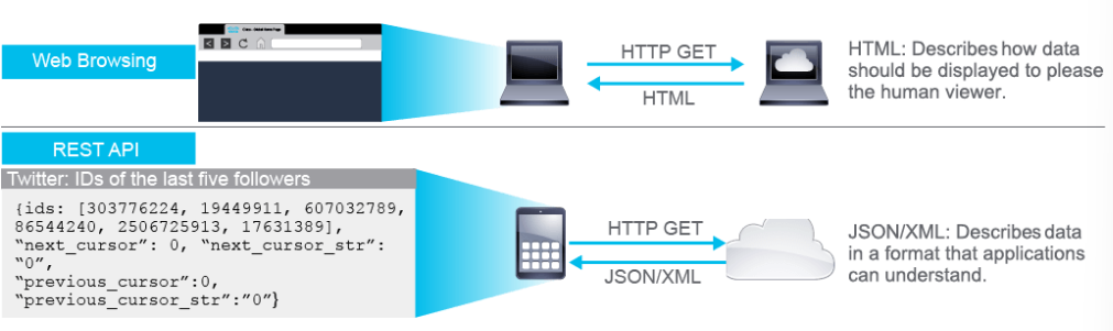
- Network Configuration Protocols (NETCONF) is an IETF standard transport protocol for communicating with network devices, retrieving operational data (statistic, memory util, error) and both setting and reading configuration data. NETCONF use SSH as transport. There are 4 layers of NETCONF protocol stack: Content, Operations, Messages, Transport
- Represent State Transfer Configuration protocol (RESTCONF) characteristics: functional subset of NETCONF, exposes YANG models via REST API (URL), use HTTP or HTTPs as transport, uses XML or JSON for encoding, developed to use HTTP tools and programming libraries, use common HTTP verbs in REST APIs.
- Google RPC is an open-source RPC framework that provides simple client development, it’s based on Protocol Buffers, which is an open source binary serialization protocol. Configuration Management Tools is practice of defining performance, functional, and physical attribute of a product and then ensuring the consistency of a systems “configuration” throughout its life.
-
Representational State Transfer (REST) is an architectural syles (versus a protocol) for designing network applications. REST uses a stateless clint-server model that typically uses HTTP(s) to make calls between entities, where resource representations are identified by a URL. REST support CRUD operations by using specific HTTP verbs. Several tools to test REST APIs: cURL, Postman, Python
- Configuration management tools offer the following benefits:
- Automate the provisioning and deployment of applications and infrastructure
- Require no knowledge of programming-they use the declarative model, not scripting
- Leverage software development practices for deployments, including version control and testing
- Common tools: are Pupper, Ansible, Chef
-
Agent vs Agentless Approach
- There are 2 models of automated configuration management:
- Intent-based model where a central server defines the required or intended state of the system. Agent-based configuration management is pull-based, and requires installation of an agent on a network device. Example Puppet and Chef.
- Automation/agentless model is an evolution of traditional CLI and SSH techniques with automation to create reusable command sets and frameworks for scalability. No agent or client is required on the target elements and accomplished through remote shell access using SSH. Example Ansible. A potential drawback is the need to ensure that the secuirty configuration on the device is kept synchronized, as any change can have a significant impact on the configuration management tool’s ability to access the switch.
- Puppet is a configuration management framework and puppets agents get installed on the devices. Agents give us the ability to regularly poll the system to constantly check the desired state and enforce configurations as needed from the cetnralized place, the Puppet Master (server). Puppet is written in the Ruby Language. Puppet Manifest is a collection of property definitions for setting the state on the device. Manifest are commonly used for defining configuration settings, but they also can be used to install software packages, copy files, and start services.
- Chef is an open source configuration management and system orchestration software. Chef will install a client on every device which would do the actual configuration. Each chef-client has a cookbook that tells how each node in your organization should be configured. The chef server stores cookbooks, the policies that are applied to the nodes. Using chef client, nodes asks the chef server for configuration details.
-
Ansible is a configuration management orchestrator born from configuration file management on Linux hosts that has extended to network applications. Ansible is a great way to organize script to allow for large collections of tasks to be run together and iterated over any number of devices. It uses an agentless push model and it leverages YAML to create Ansible playbooks. Since Ansible is agentless, it can integrate and automate any device using any API (REST APIs, SSH, NETCONF, SNMP). Ansible components are:
- Inventory: contains the hosts operated by ansible
- Modules: are the components that do the actual work in Ansible, they are what gets executed (applied) in each playbook task.
- Playbooks: is composed of one or mode plays in an ordered list. Playbooks describe the policy to be executed to the host or hosts. People refer to the playbooks as the “design plans”.
- ansible.cfg: the default config file that controls the operation of Ansible.
How ansible works:
- The ansible controller defines a playbook to describe the desired state
- The controller connects to the target device using SSH and pushes the config
- The target device applies the playbook with the plays being performed in order as defined in the playbook
- Tasks are only performed if the resource is not already in the desired state
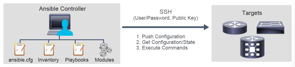 Introduction to Cisco DNA
- There are 2 models of automated configuration management:
- trend in traditional network challenges:
- There are more users and endpoints, more VLANs and subnets. It become more difficult to keep track of and segment all those groups.
- There are so many different types of users coming in to the network that is becoming more complex to configure.
- As users and devices move around the network, policy is not consistent, which makes it difficult to find users when they move around and troubleshoot issues.
- Cisco DNA Center is a cisco SDN controller for enterprise network-branch, campus, and WAN.
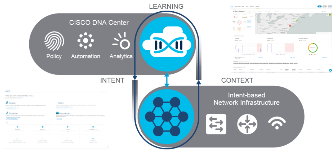
-
Intent-based Networking
- SDN is a fundational building block of intent-based networking.
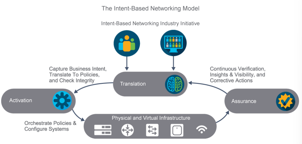
- Three foundational elements of intent-based networking:
- Translation element enables the operator to focus on what they want to accomplish and not how they want to accomplish it and it will translated to associated network policies and security policies.
- Activation once the new policies are approved and automatically deployed across the network.
- Assurance performs continuous verification that the network is operating as intended.
- SDN is a fundational building block of intent-based networking.
-
Cisco DNA Features and Tools
- Cisco DNA Center is a software solution that resides on the Cisco DNA Center Appliance. The Cisco DNA Center dashboard provides an overview of network health and helps in identifying and remediating issues.

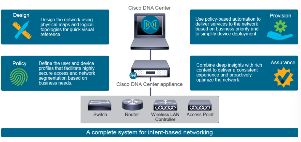
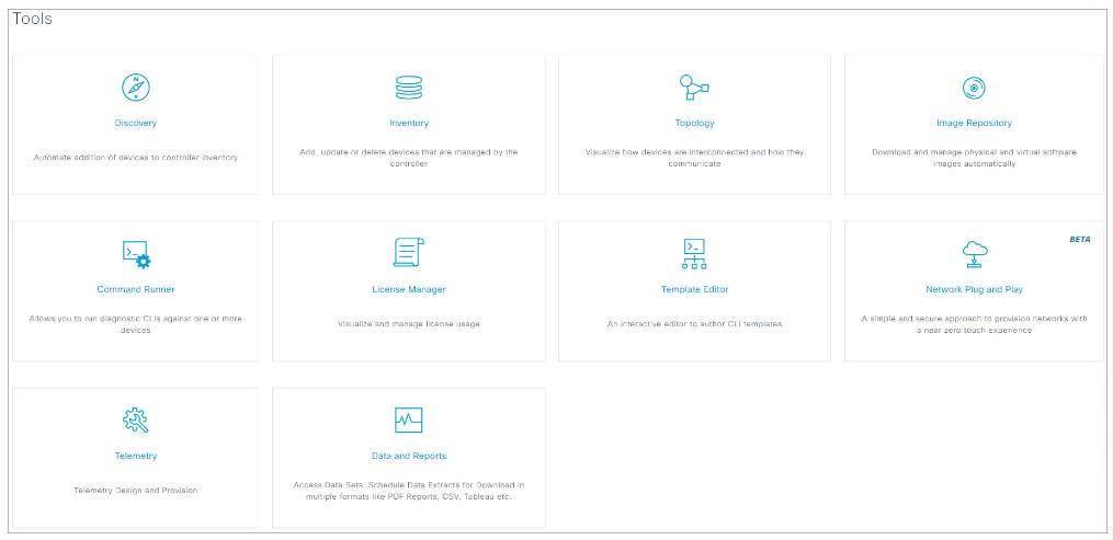
- Tools of Cisco DNA Center:
- Discovery: use to scans the network for new devices
- Inventory: use to provides the inventory for devices
- Topology: use helps you to discover and map network devices to a physical topology with detailed device-level data
- Image Repository: use to automatically download and manage physical and virtual software images
- Command runner: use to run diagnostic CLI commands against one or more devices
- License Manager: use to visualizes and manaages license usage
- Template Editor: use as an interactive editor to author CLI templates
- Network Plug n Play use to provides a simple and secure approach to provision networks with a near zero touch experience
- Telemetry: use to provides telemetry design and provisioning
- Data and Reports: use to provides access to data sets and schedules data extracts for download in multiple formats like PDF reports, comma-separated values (CSV), tableu, and so on.
- Cisco DNA Center is a software solution that resides on the Cisco DNA Center Appliance. The Cisco DNA Center dashboard provides an overview of network health and helps in identifying and remediating issues.
-
Using Cisco DNA Center for Path Tracing
- Cisco DNA center path trace allows you to examine the path that a specific type of packet travels as it makes its way across the network from a source to destination node. The output for a path trace consists of two elements:
- The graphical displayy of the path between the hosts
- The list of each device along the path, with details about the interfaces.
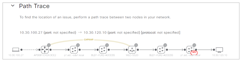
- Cisco DNA center path trace allows you to examine the path that a specific type of packet travels as it makes its way across the network from a source to destination node. The output for a path trace consists of two elements:
Cisco DNA Simulations
-
Explore Cisco DNA Center
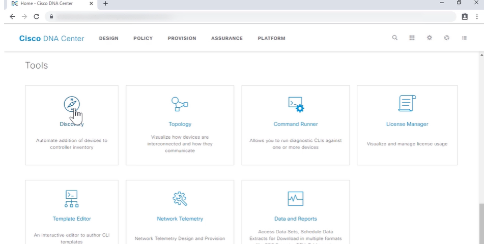
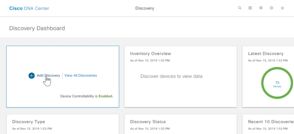
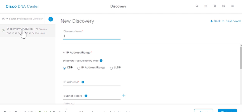
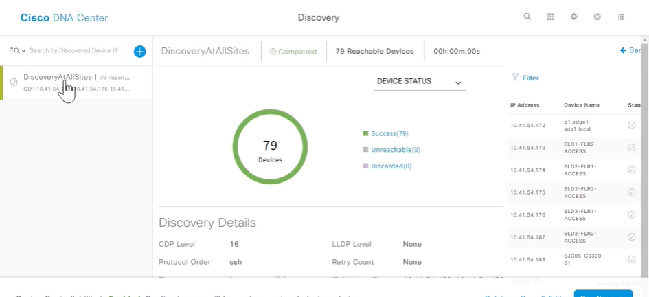
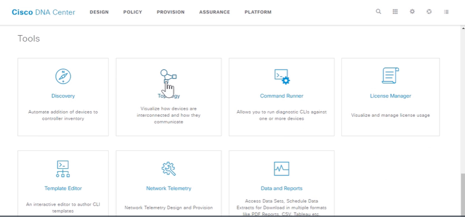
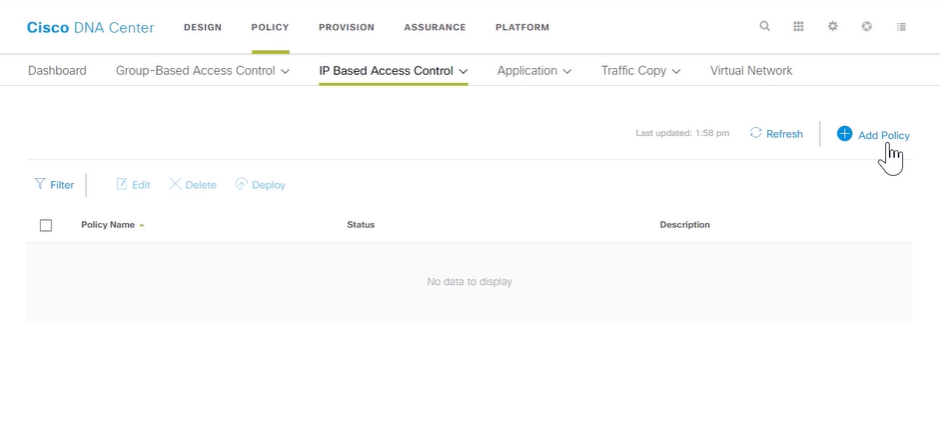
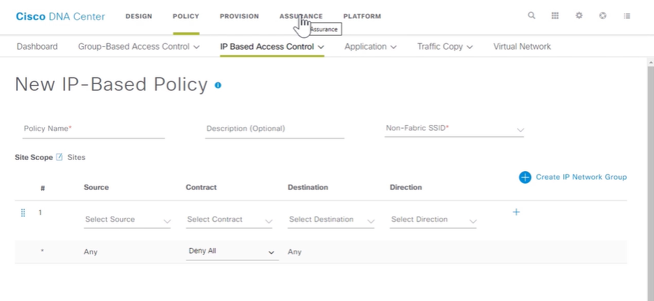
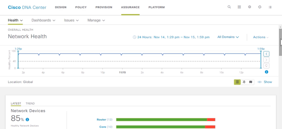
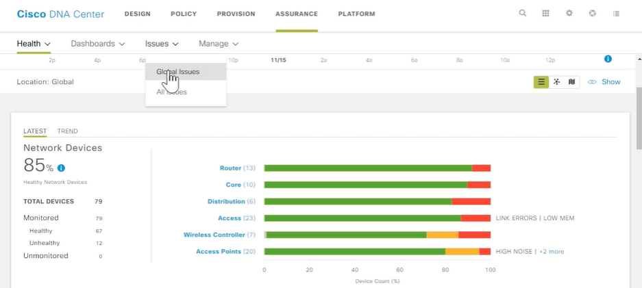
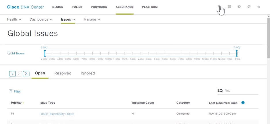

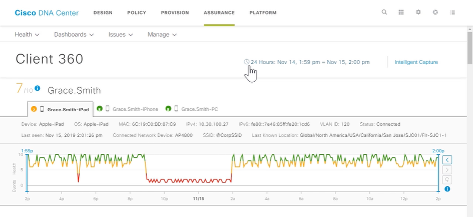
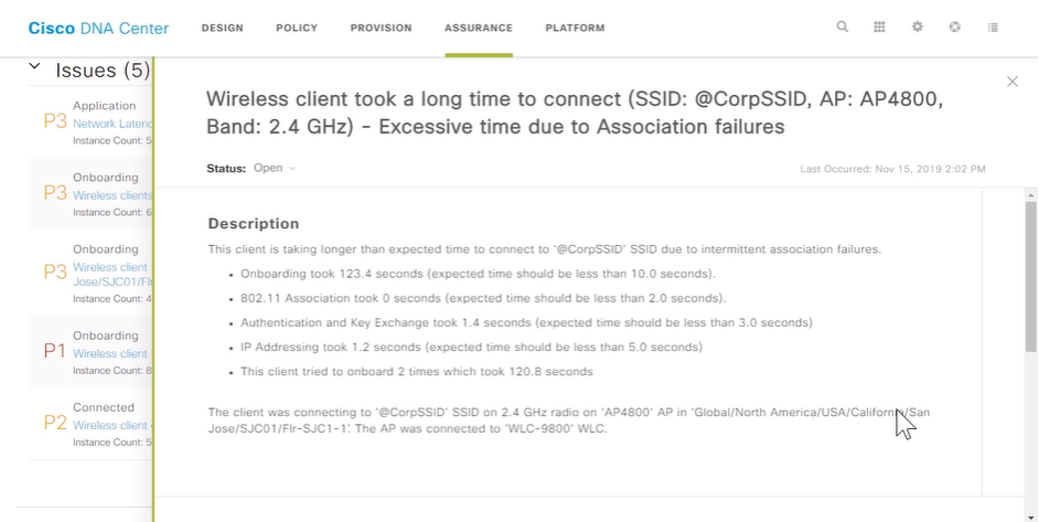
Cisco SD-Access
-
The Cisco Software-Defined Access (SD-Access) solution is a programmable network architecture that provides software-based policy and segmentation from the edge of the network to the applications. SD-Access is implemented via Cisco DNA Center. Cisco SD-Access comprises these elements:
- Cisco DNA Center: automation, policy, assurance, and integration infrastructure
-
SD-Access fabric: physical and logical network forwarding infrastructure
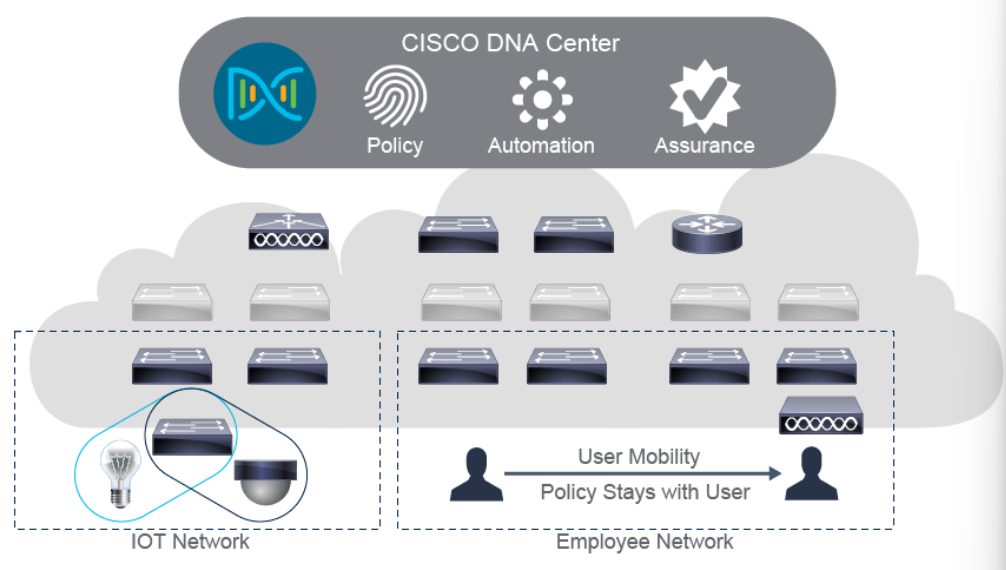
- SD-Access Management with Cisco DNA Center Cisco DNA Center provides a central management plane for building and operating an SD-Access fabric. The management plane is responsible for forwarding configuration and policy distribution, as well as device management and analytics. There are 2 main function Cisco DNA Center: Automation and Assurance. DNA Center automation provides the definition and management of SD-Access group-based policy, along with the automation of all policy-related configuration. The Network Assurance quantifies availability and risk from an IT network perspective, based on a comprehensive set of network analytics.
-
SD-Access Fabric is combination of an underlay (physical devices and forwarding of traffic) and overlay (entirely virtual layer where wireless and wired users and devices are logically connected together, and service policy applied)
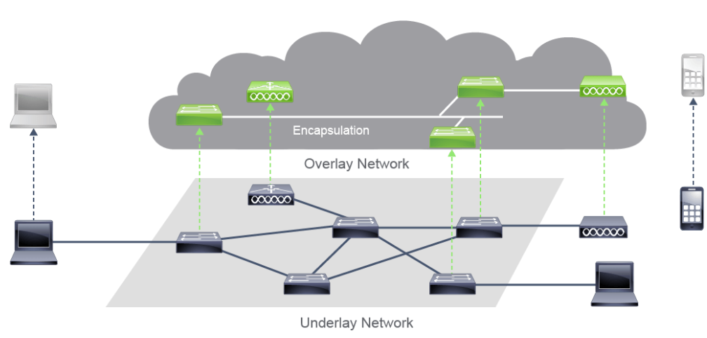 There are three primary types of policies that can be automated in the SD-Access fabric:
- Security: Access Control policy, which dictates who can access what
- QoS: Application policy, which invokes the QoS service to provision differentiated access to users on the network, from an application experience perspective
- Copy: Traffic copy policy, which invokes the traffic copy service for monitoring specific traffic flows
-
SD-Access Benefits include the following:
- Automation: Plug-and-play for simplified deployment of new network devices, along with consistent management of wired and wireless network configuration provisioning
- Policy: Automated network segmentation and group-based policy
- Assurance: Contextual insight for fast issue resolution and capacity planning
- Integration: Open and programmable interfaces for integration with third-party solutions.
Cisco SD-WAN
-
Cisco SD-WAN is a software-defined approach to managing WANs and used to simplifies the management and operation of a WAN by separating the networking hardware from its control mechanism. The Cisco SD-WAN Solution is comprised of separate orchestration, management, control, and data planes:
- Orchestration plane assists in the automatic onboarding of the SD-WAN routers into the SD-WAN overlay.
- Management plane is responsible for centralized configuration and monitoring.
- Control plane builds and maintains the network topology and makes decisions on where traffic flows
-
Data plane is responsible for forwarding packets based on decisions from the control plane
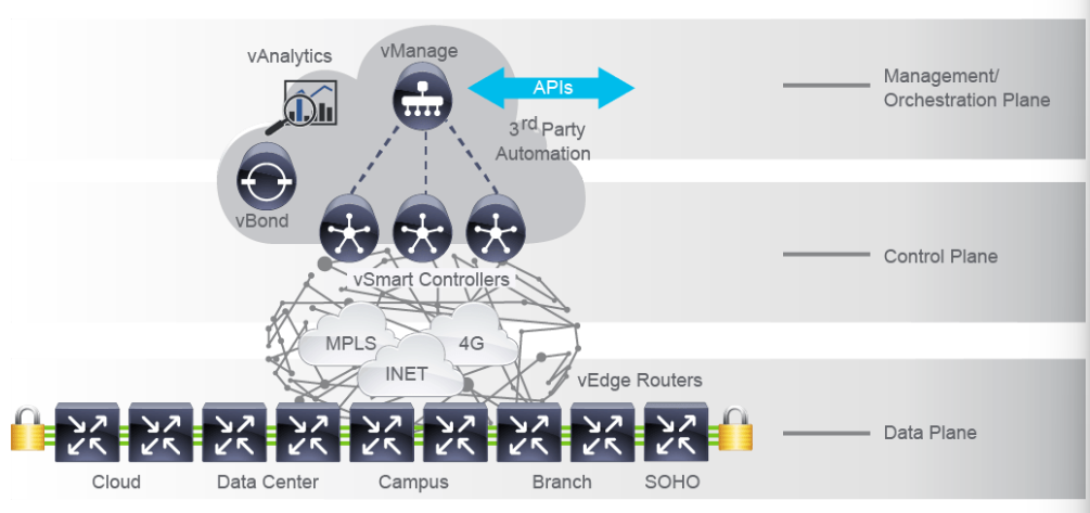
- The primary components of Cisco SW-WAN:
- Management Plane (vManage): centralized network management system provides a GUI interface to monitor, configure, and maintain all Cisco SD-WAN devices and links in the underlay and overlay network.
- Control Plane (vSmart Controller): responsible for the centralized control plane of the SD-WAN network. It establishes a secure connection to each vEdge router and distributes routes and policy information via the Overlay Management Protocol.
- Data plane (vEdge Router): the device, available as either a hardware appliance or software-based router, sits at a physical site or in the cloud and provides secure data plane connectivity among the sites over one or more WAN transports.
- Programmatic APIs (REST): programmatic control over all aspects of vManage administration.
- Analytics (vAnalytics): adds a cloud-based predictive analytics engine for Cisco SD-WAN.
28. Introducing System Monitoring
Introducing Syslog
-
Syslog is a protocol that allows a device to send event notification messages across IP network to event messages collectors. Syslog messages can be sent via UDP (port514) or TCP (port6514). Here are common syslog messages that you may seen:
%SYS-5-CONFIG_I: Configured from console by console
%LINK-3-UPDOWN: Interface FastEthernet0/0, changed state to down
Syslog Message Format
-
Priority : is an 8-bit number and its value represents the facility and severity of the message.
- Facility is integer values that broadly categorized based on the sources that generate them (OS, process, application). Example Cisco IOS Software-based devices use facility local7.
- Severity the log source or facility that generates the syslog messages specifies the severity of the message using single-digit integers 0-7. 0=Emergency, 1=Alert, 2=Critical, 3=Error, 4=Warning, 5=Notification, 6=Informational, 7=Debugging.
-
Header contains these fields:
- Time Stamp is used to include the local time of the sending device when the message is generated. Every devices need to use NTP for the accurate time stamp.
- Hostname consist of the hostname or the IP address.
-
Syslog MSG is the text of the syslog message, with additional information about the process that generated the message.
-
How to Read System Messages
-
The general format of syslog messages that syslog process are structured as follows:
seq no:timestamp: %facility-severity-MNEMONIC:description

*Apr 22 11:05:55.423: %LINEPROTO-5-UPDOWN: Line protocol on Interface FastEthernet0/22, changed state to up
Facility codes in syslog message:
- LINEPROTO : Line protocol
- LINK : Data Link
- OSPF : Open Shortest Path First
- CDP : Cisco Discovery Protocol
- SYS : Operating System
########## Change Sequence Number ############
R1(config)# service sequence-numbers
R1(config)# end
R1#
000047: Apr 10 05:24:07.660: %SYS-5-CONFIG_I: Configured from console by console

######### Turn off timestamp ###############
R1(config)# no service timestamps
R1(config)# end
R1#
000048: %SYS-5-CONFIG_I: Configured from console by console

######## messages with listed in order of severity ##########
%PLATFORM_ENV-1-PWR: Faulty internal power supply detected
%LINK-3-UPDOWN: Interface FastEthernet0/0, changed state to down
%SYS-5-CONFIG_I: Configured from console by console
%SEC-6-IPACCESSLOGDP: list dmz-acl denied icmp 10.10.10.2 -> 10.10.99.1
-
-
System Log Config
- To change the level of messages that are sent to the console, use the
logging console <level>command. Limit the syslog messages that are sent to the syslog server based on the severity:R1(config)# logging host 10.1.1.10 R1(config)# logging trap informational R1(config)# logging source-interface Loopback0
Command Description logging{hostname/ip-address}Identifies a syslog server host to receive logging messages logging host{hostname/ip-address}Accomplishes the same thing as the loggingip-addresscommand, used to send syslog messages to the multiple syslog serverslogging trapseverityLimits the syslog messages that are sent to the syslog server based on the severity level. logging source-interfaceinterfaceIdentifies which interface is used as source IP address, when syslog messages will be sent Check syslog messages that are stored in the router and shows you how many messages are logged to various destinations, and what severity level is configured for that destination.
R1# show logging Syslog logging: enabled (0 messages dropped, 3 messages rate-limited, 0 flushes, 0 overruns, xml disabled, filtering disabled) No Active Message Discriminator. No Inactive Message Discriminator. Console logging: level debugging, 29 messages logged, xml disabled, filtering disabled Monitor logging: level debugging, 0 messages logged, xml disabled, filtering disabled Buffer logging: level debugging, 29 messages logged, xml disabled, filtering disabled Exception Logging: size (4096 bytes) Count and timestamp logging messages: disabled Persistent logging: disabled No active filter modules. Trap logging: level informational, 32 message lines logged Logging to 10.1.1.10 (udp port 514, audit disabled, link up), 5 message lines logged, 0 message lines rate-limited, 0 message lines dropped-by-MD, xml disabled, sequence number disabled filtering disabled Logging Source-Interface: VRF Name: Loopback0 Log Buffer (4096 bytes): <... output omitted ...> *Apr 10 14:37:21.630: %SYS-5-CONFIG_I: Configured from console by console *Apr 10 14:37:23.019: %LINK-3-UPDOWN: Interface Ethernet0/1, changed state to up *Apr 10 14:37:24.023: %LINEPROTO-5-UPDOWN: Line protocol on Interface Ethernet0/1, changed state to up <... output omitted ...> - To change the level of messages that are sent to the console, use the
-
How to Read System Messages
SNMP Overview
- Use case: Using SNMP to gather information
- SNMP Versions
Enabling Network Time Protocol
- Software Clock
- Hardware Clock
- Network Time Protocol
- Configuring and Verifying NTP
Configure and Verify NTP
Configure System Message Logging
29. Managing Cisco Devices
Cisco IOS Integrated File System and Devices Stages of the Router Power-On Boot Sequence Loading and Managing System Images Files Loading Cisco IOS Configuration Files Validating Cisco IOS Images using MD5 Managing Cisco IOS Images and Device Config Files
Create the Cisco IOS Image Backup
  R1# ping 172.16.1.100 --> success ping tftp server
  R1# sh flash
  1   50MB  Nov 9 2019  23:36:24  +00:00  installer.bin
  13MB available (50MB used)

  R1# copy flash: tftp:
  Source filename []? installer.bin
  Address or name of remote host []? 172.16.1.100
  Destination filename [installer.bin]?
Upgrade Cisco IOS Image
  R1# sh ver
  system image file is "flash:installer.bin"

  R1# sh flash
  1   50MB  Nov 9 2019  23:36:24  +00:00  installer.bin
  13MB available (50MB used)

  R1# del flash:installer.bin
  R1# sh flash
  64MB bytes available (0 bytes used)

  R1# copy tftp: flash:    ---> copy from tftp: server download to flash:
  Address or name of remote host []? 172.16.1.100
  Source filename []? installer.bin

  R1# sh flash
  1   51MB  Nov 9 2019  23:36:24  +00:00  installer2.bin
  12MB available (51MB used)

  R1# conf t
  R1(config)# boot system flash installer2.bin
  R1(config)# exit
  R1# copy run start
  R1# sh ver
  system image file is "flash:installer.bin"

  R1# reload
  R1# sh ver
  system image file is "flash:installer2.bin"
Upgrade Cisco IOS Image from TFTP server
  1. Change IPv4 on Ethernet Adapter
      - Control Panel > Network & Internet > Network Connection > Eth Properties > IPv4 Properties
        IP Address  : 192.168.10.1
        Subet mask  : 255.255.255.0
        Default GW  : 192.168.10.2

  2. Open TFTPd64 Application
     Current Directory : C:\Users\ZZ00TH749\Desktop
     Server Interface  : 192.168.10.1

  3. Open Putty
     Serial Line  : COM1
     Speed        : 9600
     Connection   : Serial

  4. Backup config
    SW1# term leng 0
    SW1# show run

  5. Verify active zone
    SW1# sh zone analysis vsan <ID>
    SW1# sh zone analysis active vsan <ID>

  6. Verify the storage displayed in the fabric log
    SW1# sh flogi database
    SW1# sh flogi database vsan <ID>

  7. Pre-check verification
    SW1# ping 192.168.10.2
    SW1# sh bootflash:                --> make sure the disk space is enough
    SW1# sh system internal flash     --> make sure the /var log folder is not full
    SW1# sh system internal dir /var  --> troubleshoot what causing it full
    SW1# sh feature | i scp           --> make sure it disabled
    SW1# sh feature | i ftp           --> make sure it disabled
    SW1# sh version                   --> capture current version

  8. Copy running config & startup config
    SW1# copy run bootflash:running-config-23032023.cfg

  9. Transfer file from Switch to TFTP Server
    SW1# copy flash: tftp:            --> try to copy from switch to PC
    Source filename []? running-config-23032023.cfg
    Address or name of remote host []? 192.168.1.150   --> PC IPv4

    SW1# copy flash: tftp:            --> try to copy from switch to PC
    Source filename []? installer.bin
    Address or name of remote host []? 192.168.1.150   --> PC IPv4

  10. Download file from TFTP server to Switch
    SW1# copy tftp: flash:
    Address or name of remote host []? 192.168.1.150
    Source filename []? installer2.bin

    SW1# sh bootflash:

  11. Checksum MD5 to make sure file is not corrupt
    SW1# verify /md5 bootflash:installer2.bin
    OR
    SW1# show file bootflash:installer2.bin md5sum

  12. Check feature incompatibility
    SW1# show incompatibility system bootflash:m9100-s5ek9-mz.8.4.2d.bin
    SW1# show install all impact kickstart m9100-s5ek9-kickstart-mz.8.4.2d.bin system m9100-s5ek9-mz.8.4.2d.bin

  13. Save the current configuration
    SW1# copy run start

  14. Firmware installation with non-disruptively
    SW1# install all system bootflash:m9100-s5ek9-mz.8.4.2d.bin kickstart bootflash:m9100-s5ek9-kickstart-mz.8.4.2d.bin

  15. Final verification
    SW1# sh version
    SW1# sh zone analysis vsan <ID>
    SW1# sh zone analysis active vsan <ID>
    SW1# sh flogi database
    SW1# sh flogi database vsan <ID>


  BACKUP PLAN use SCP
  ---------------------
  SW1# sh feature | i scp
  SW1# conf t
  SW1(config)# feature scp-server

  PC1# ping 136.61.206.3
  PC1# scp m9100-s5ek9-kickstart-mz.8.4.2d.bin RYANTHOV@136.61.206.3:bootflash:m9100-s5ek9-kickstart-mz.8.4.2d.bin
  PC1# scp m9100-s5ek9-mz.8.4.2d.bin RYANTHOV@136.61.206.3:bootflash:m9100-s5ek9-mz.8.4.2d.bin
30. Examining the Security Threat Landscape
Security Threat Landscape Overview
Security Concepts about threat:
- Threat: event with potential to cause harm to an asset (example: malicious software)
- Vulnerability: A weakness that compromises the security or functionality of a system.
- Exploit: uses a vulnerability to compromise the security or functionality of a system.
- Risk: attack will exploit a particular vulnerability of an asset that results in an undesirable consequence.
- Mitigation techniques: method and corrective actions to protect againts threats.
Malware
Malware is malicious software such as:
- Viruses: propagates by inserting a copy of itself into another program and becoming part of the program, but it’s need human help to propagate.
- Worms: replicate functional copies of themselves and can cause the same type of demages without human help.
- Trojan Horses: harmful pieces of software that looks legitimate but damaging the host, and it’s not self-replicate.
Hacking Tools
Hacking or security tools:
- sectools.org: website run by Nmap Project, which regularly pollsthe network security community regarding their favorite security tools.
- Kali linux: a live Linux Distribution that ran from CD-ROM and included more than 100 security tools.
- Metasploit: framework is distributed with hundred of exploit modules and dozens of payload modules. and the exploit targets a vulnerability of an unpatched OS or application server.
DoS and DDoS
DoS (Denial of Service) or DDoS (Distributed DoS) attacks attempt to consume all critical computer or resources to make them unavailable for proper use. (example: TCP syncronization flood attack). An attacker creates packets with random IP sources addresses with IP spoofing to obfuscate the actual originator. A botnet consists of a group of “zombies” program that control mechanism that provides directions. Botnet typically operates in this manner:
- infects computers by infecting with malicious code which run the malicious bot process.
- The bot on newly infected host logs into the command and control server and awaits commands.
- Instructions are sent from the command and control server to each bot in the botnet to execute actions.
Spoofing
Spoofing attack when an attacker injects traffic appears to be sourced from system other than the attacker’s systems itself:
- IP address spoofing: attackers inject a source IP address in the IP header of packets different from their real IP addresses.
- MAC address spoofing: attacker use MAC addresses to exploit weaknesses at Layer 2 of the Network.
- Application or service spoofing: the attackers enables a rouge DHCP server on a network. An attacker can spoof many DHCP client request from the client-side, specifying a unique MAC address per request.
Reflection and Amplification Attacks
A reflection attack is a type of DoS attack in which attacker sends a flood of protocol request packets to various IP hosts. Smurf attacks can easily be mitigated on a Cisco IOS device by using the no ip directed-broadcast interface config command. This will accomplish to drop broadcast destined for the subnet to which that interface is attached.
Social engineering
Social engineering is manipulating people to capitalize on expected behaviors. Social engineering often involves utilizing social skills, relationships, or understanding of cultural norms to manipulate people inside a network to provide the information that is needed to access the network. For example:
- calling users to change password
- sending an infected USB key along with book or magazine samples
- sending email enticing a user to click a link to a malicious website (phising)
- visual hacking, where attacker physically observes the victim entering credentials
Evolution of Phising
Phising is sending an email and enticing users to click a link to a malicous websites.
- Spear phishing: email send to smaller targeted group that allows the attacker to craft an email that is more likely to deceive the target successfully.
- Whaling: same with spear phising but targeting a high profile target that designed to get an executive’s attention.
- Pharming: entices the victim to malicous website by injecting entries into localhost files or by poisoning the DNS in some fashion.
- Watering hole: uses a compromised web server to target select groups. First, determine the target website. second, infecting them with malware that can identify members of target. It makes difficult to recognize watering holes by analyzing web traffic.
- Vishing: uses the same concept as phising, except that it uses voice and the phone system as its medium instead of email.
- Smishing: uses the short message service (SMS) texting as the medium instead of email.
Password Attacks
Several method for obtaining user passwords:
- Guessing: attacker can manually enter password or use a software tools to automate process.
- Brute force: use password cracker to performs a brute force crack by systematically trying every possible password until it succeeds.
- Dictionary Attacks: use word list to structure login attempts. it’s not always successful and are often attempted before a brute force attack.
Reconnaissance Attacks
A reconnaissance attack attempts to learn more about the intended victim before attempting a more intrusive attack. use standard networking tools such as dig, nslookup, whois to gather informations.
Buffer Overflow Attacks
attacker can provide a larger than expected buffer input, and service will accept the input and write it to memory, filling up the associated buffer and overwriting adjacent memory. It will corrupt the system and cause it to crash, resulting in a DoS. and the worse the attacker can inject malicious code.
Man-in-the-Middle Attacks
Is a generalized concept that can view the communication between two systems imposes itself in the communication path between those other systems which resulting misdirection of traffic.
Vectors of Data Loss and Exfiltration
Common vectors of data loss and exfiltration:
- Email attachments: Email might be intercepted or user accidentally send the email to wrong person.
- Unencrypted devices: unencrypt personal device to steal corporate data and perhaps even gain unauthorized access to the company network.
- Cloud Storage services: theft of sensitive documents bys omeone like a social network “friend” with whom the employee shares a directory on the cloud storage server.
- Removable storage devices: removable storage can easily stolen or lost, and it’s not encrypted
- Improper access controls: risk data lost when inproper access control lists on firewall
31. Implementing Threat Defense Technologies
Information Security Overview
Protection must guarantee three things:
- Confidentially: providing confidentiality of data guarantees that only authorized users can view sensitive information.
- Integrity: providing integrity of data guarantees that only authorized users can change sensitive information.
- System and Data Availability: providing system and data availability guarantees uninterrupted access by authorized users to important computing resources and data.
a security awareness and training program should encompass these 7 steps:
- Identify program scope, goals, and objectives
- Identify training staff
- Identify target audiences
- Motivate management and employees
- Administer the program
- Maintain the program
- Evaluate the program
Firewalls
A firewall is a system that enforces an access control policy between two or more security zones. Firewall should have these properties:
- must resistant to attack
- all traffic must flow through the firewall
- must have traffic-filtering capabilities
Cisco Firewall have these capabilities:
- provide highly effective threat and advanced malware protection
- Implement policies based on application visibility
- Provide URL filtering and other controls over web traffic
- Provide actionable indications of compromise to identify malware activity
- Offer comprehensive network visibility
- Help reduce complexity
- Integrate and interface smoothly with other security solutions
Intrusion Prevention Systems
An IPS is a system that performs depp analysis of network traffic, searching for signs of suspicious or malicious behavior. IPS can detect and block wide range of malicious behaviour. Several methods of traffic inspection used in IPS:
- Signature-based inspection: a signature-based IPS examines the packet headers and data payloads in network traffic and compares the data against a database of known attack signatures.
-
Anomaly-based inspections: observe network traffic and act if a network event outside network behavior is detected.
- Statistical anomaly detection: observes network traffic over time and builds a statistical profile of normal traffic behavior based on communication patterns, traffic rate, mixture of protocols, and traffic volumes.
- Protocol verification: observe network traffic and compares network, transport, and application layer protocols that are used inside network traffic protocol to standards.
- Policy-based inspection policy-based IPS analyzes network traffic and takes action if it detects a network event outside a configured traffic policy.
Protection Against Data Loss and Phising Attacks
By applying the right mix of social engineering techniques. Or use Cisco tools:
- Cisco ESA (Email Security Appliance) all in one appliance againts spam, advanced malware, phising, data loss by filtering unsolicited and malicious email before it reaches the user.
- Cisco WSA (Web Secure Appliance) offer multiple anti-malware scanning engines on a single, integrated appliance which use Cisco Dynamic Vectoring and Streaming engine, webroot, sophos, and McAfee to protect web-based threats.
Defending Against DoS and DDoS Attacks
Two types DoS attacks, volumetric and application-level.
Introduction to Cryptographic Technologies IPsec Security Services Secure Sockets Layer and Transport Layer Security Wireless Security Protocols Configure WLAN using WPA2 PSK using GUI
32. Securing Administrative Access
Network Device Security Overview Securing Access to Privilleged EXEC Mode Securing Console Access Securing Remote Access Secure Console and Remote Access Configuring the Login Banner Limiting Remote Access with ACLs Enable and Limit Remote Access Connectivity External Authentication Options Secure Device Administrative Access
33. Implementing Device Hardening
Securing Unused Ports Infrastructure ACL Disabling Unused Services Port Security Configure and Verify Port Security Mitigating VLAN Attacks DHCP Snooping Dynamic ARP inspection Mitigating STP Attacks Implement Device Hardening
Glossary:
-
Section 18:
-
STP (SPanning Tree Protocol): is used as a Layer2 loop prevention mechanism while still providing network link redundancy.
- RSTP (Rapid STP): faster coverage delay after topology change than the traditional STP.
- PVST+ (per VLAN STP): add vlan tag on the spanning tree operation
- BPDUs (Bridge Protocol Data Units): contain information about the spanning tree protocol (STP) used for communication between switches.
- TTL (Time to Live): hop limits mechanism that limits the number of times that a Layer3 networking device can retransmit a packet or limit how many Layer3 devices a packet can traverse.
- BPDU Guard: feature that defends the L2 STP against BPDU threats and is designed to protect the switch network.
- PortFast: used on access ports to bypass the listening and learning state of STP
-
STP (SPanning Tree Protocol): is used as a Layer2 loop prevention mechanism while still providing network link redundancy.
-
Section 19:
- Port Channel: provides the aggregate bandwidth of several physical links
-
Section 20:
-
FHRP (First Hop Redundancy Protocols): are a group of protocolss with similar functionality that enable a set of routers or Layer3 switches to present an illusion of a “
Virtual” router. - HSRP:
- ARP (Address Resolution Protocols): to resolve the MAC address of the default gateway. It’s a procedure for mapping a dynamic IP address to permanent MAC address in LAN.
-
FHRP (First Hop Redundancy Protocols): are a group of protocolss with similar functionality that enable a set of routers or Layer3 switches to present an illusion of a “